
Understand the 74HC595

The circuit design incorporates the 74HC595 shift register, which is an 8-bit serial-in, parallel-out shift register, to manage multiple Triac drivers. Each output (Q1 through Q7) from the 74HC595 is connected to the gate of a corresponding Triac through a limiting resistor. The Triacs are responsible for switching the 110VAC load. The 5 VDC signal from the shift register is used to trigger the Triacs, allowing for control over high voltage AC loads.
When implementing this circuit, it is essential to consider the total number of 74HC595N chips being utilized. In larger systems, a desktop PC is preferred due to its ability to provide higher voltage levels, which is crucial for reliable operation of multiple ICs. If a laptop is necessary, the design must include voltage regulation components to ensure that the 5 VDC supplied to the 74HC595N chips is appropriate for their operation.
The output pulse width from the parallel port must be sufficient to ensure that the 74HC595N chips recognize the input signals correctly. If the pulse width is inadequate, the chips may fail to trigger the Triacs reliably, leading to erratic channel behavior. Adjusting the limiting resistor value is also critical, as it determines the gate current supplied to the Triacs. If the resistor value is too high, the Triacs may not turn on, while a value that is too low could potentially damage the Triacs or the driving ICs.
In summary, careful attention must be paid to the voltage levels, output pulse widths, and resistor values in this circuit design to ensure reliable operation of the Triac drivers and the controlled AC loads.The Triac drivers use the 5 VDC output signal from the 74HC595 chip outputs (Q1, Q2, Q3, Q4, Q5, Q6, and Q7) to switch the 110VAC gate signal to the Triacs. If you are connecting the IC chips directly to the PC, a desktop PC MUST BE USED to drive the electronics in a large system because a laptop computer does not have the voltage required to run
a large quantity of 74HC595N chips. A laptop can be used in smaller systems (16 channels) but the voltage to the 74HC595N IC chips will need to be lowered since a laptops output voltage is lower than that of a desktop. Add on PCI cards tend to have a lower voltage. Also don`t expect to drive as many IC chips with a laptop as compared to your desktop. In some cases, the parallel port of a desktop will not provide sufficiently high pulses and the Vcc (5 volts DC) to the 74HC595N chips needs to be lowered so the 74HC595 can "see" the pulses from the parallel printer port.
The symptom results in some channels working and others not and channels triggering out of order. Here is the catch, if you lower the voltage to the IC chips then the voltage from the outputs of the IC chips also gets lowered and the current from the outputs gets lowered. It may be necessary to lower the value of the limiting resistor from the 74HC595N chip output to the triac driver in order to properly trigger the triac drivers.
🔗 External reference
Related Circuits
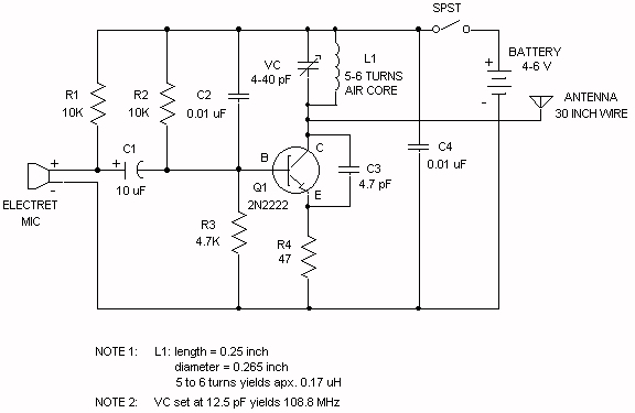
The electret microphone operates with a current of 200 µA, which varies by ±3 µA in response to sound waves. This variation results in a voltage of 2V across resistor R1 and 4V across the microphone. As sound waves...
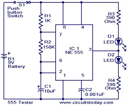
This schematic requires clarification. It is assumed that pin 2 is connected by a wire to pin 6, although this connection appears to be unclear. The circuit in question involves a schematic where pin 2 and pin 6 are interconnected....
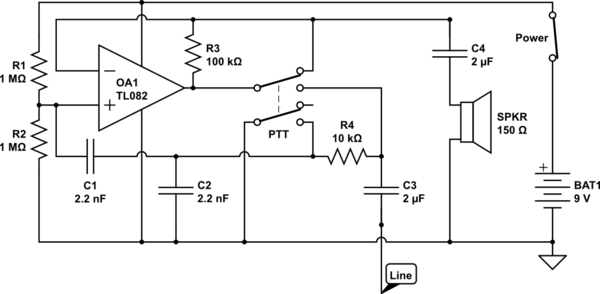
The circuit operates in receive mode, with the Push-To-Talk (PTT) switch enabling transmit mode. The speaker functions as both a microphone and a speaker. Most systems observed utilize a rocking armature transducer for the speaker. There is no base...
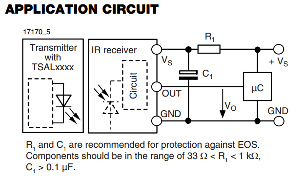
There is an interest in starting an introductory electronics project using an infrared (IR) sensor, but there is some confusion regarding the application circuit provided in the datasheet. The recommended resistor value is significantly lower than the calculated value....
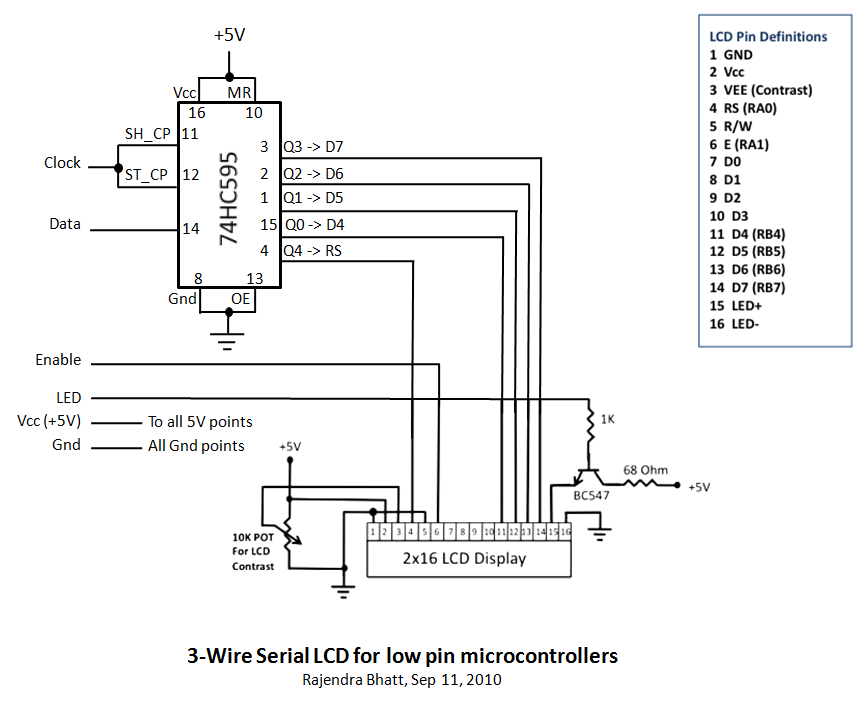
Library routines for a 3-wire LCD interface utilizing the 74HC595 shift register. Additional details can be found in the attached ReadMe document or on the associated webpage. The library routines for the 3-wire LCD interface are designed to facilitate communication...
WB5LUA described GaAsFET preamplifiers for several microwave bands, which included an active bias circuit for the GaAsFET. Although newer devices have been introduced that offer improved performance, they require different bias points with varying currents and voltages. Modifying the...