
Transmitter - Received AM radio
This circuit design emphasizes the importance of the resonator filters in frequency selection and amplification, which are critical for effective transmission. The ceramic resonator's stability at 3.587 MHz provides a reliable frequency reference, while the additional frequencies available from the filters allow for versatility in applications. The amplification stages, particularly with the use of transistors T1, T2, and T3, are crucial for boosting the signal strength to the antenna, ensuring that the transmission can reach the intended distance of 2-4 km.
The integration of the MK484 IC streamlines the overall design by incorporating multiple functions necessary for AM radio operation, such as RF amplification and automatic gain control, which enhances the quality of the received signal. The use of a BC108B transistor as a voltage regulator ensures that the circuit operates efficiently and with minimal noise, while the carefully selected passive components, including diodes and resistors, contribute to the circuit's overall stability and performance.
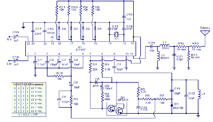
The trimpot allows for fine-tuning of the circuit, enabling adjustments to be made for optimal selectivity, which is especially important in crowded frequency environments. The Class A and Class B amplifier configuration further enhances signal fidelity and power efficiency, making this circuit suitable for various AM broadcasting applications. Overall, this design showcases a well-rounded approach to creating a reliable AM transmitter capable of operating within the specified frequency range and achieving the desired transmission distance.Using ceramic tuning 3. 587 mhz resonator and resonator filters are also sold with a value of 5. 5mhz, 7. 7 mhz and 10. 7 mhz. Distance transmitter range is approximately 2-4km. the working principle of this circuit are filter resonator/ceramic filtersraise the frequency of the value of the resonator filter. This frequency is amplified by the transistor can be changed t1. Frequency so need C7 as a regulator / placement. sound signalsuperimposed over the audio transformer. frekuensi which awakened byresonator filters and t1 is fed to the next amplifystrengthened so as to achieve the desired power passed toantenna. t2 and t3 as a buffer as a final power amp. For AM radio because it`s hard to find IC ZN 414then now could be replaced with the equivalent of IC MK 484.
Frequency coverage between 550 kHz-1600 mhz, 3 pins of this IC includeseries of radio tuner, RF amplifiers, automatic gain control, the AM detector. The series voltage regulator or a power transistor made by BC108B, 4diada IN 4148, 2k7, 820R, and the 10K trimpot, trimpot functions forselectivity of the controller of all series.
Then weusing a booster class A and class B amplifier for signalmodulated not disappear. 🔗 External reference
Related Circuits
The circuit presented is a high-quality Stereo FM transmitter capable of transmitting signals up to a range of 70 feet. It utilizes the BH1417 PLL stereo transmitter IC from Rohm Semiconductors, which features separate audio processing sections for left...
If a complete circuit is needed, there are thousands of these circuits available in the designs. Some of them can be provided easily, but further communication is required. The request indicates a need for a comprehensive circuit design, which may...
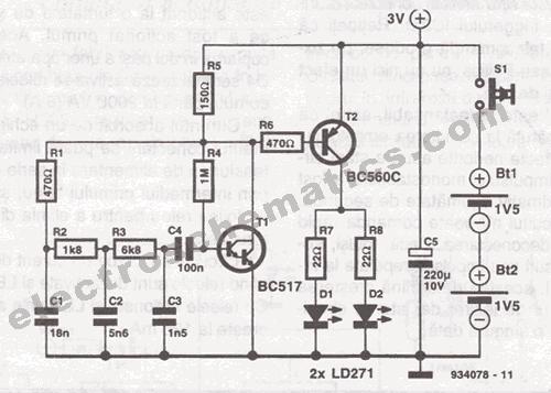
This infrared transmitter is designed for use with an infrared receiver. It operates using either two 1.5V batteries or a 3V lithium battery, allowing for a compact infrared communication system. The infrared transmitter circuit typically consists of an infrared LED,...
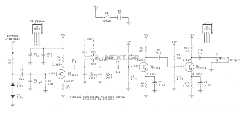
This version sports a 2nd audio amplifier stage at Q3. The output level with this version is sufficient to drive a crystal headphone to a comfortable volume. The "crystal" headphone is like those used on ye olde crystal radios....
The circuit consists of a frequency modulated oscillator, an audio preamplifier with pre-emphasis to supply the frequency modulating signal, and a buffer amplifier to drive the antenna connector. Oscillator's frequency is determined by L1 resonating with the 10 pF...
Radio-Circuits has elevated the standard with this website. Unlike any other circuit site on the internet, they have compiled ten of the most popular FM transmitter circuits. Radio-Circuits provides a comprehensive collection of FM transmitter circuits, showcasing a variety of...
Warning: include(partials/cookie-banner.php): Failed to open stream: Permission denied in /var/www/html/nextgr/view-circuit.php on line 713
Warning: include(): Failed opening 'partials/cookie-banner.php' for inclusion (include_path='.:/usr/share/php') in /var/www/html/nextgr/view-circuit.php on line 713