
TRIAC

The TRIAC (Triode for Alternating Current) is extensively utilized in AC power control applications due to its ability to conduct current in both directions. This unique capability allows it to control the power delivered to loads such as lamps, motors, and heaters, making it ideal for dimming, speed control, and heating applications. The TRIAC operates by using a gate terminal to trigger conduction, which can happen at any point in the AC cycle, thereby providing versatility in control.
In practical applications, TRIACs are often used in light dimmers, motor speed controllers, and solid-state relays. The device can be triggered by a small current applied to the gate, allowing it to control larger currents through the main terminals without the need for additional components like diodes for triggering, as is required with SCRs. This characteristic simplifies circuit design and enhances reliability.
When implementing a TRIAC in a circuit, it is essential to consider the snubber circuits for protection against voltage transients, which can occur during switching. Additionally, proper heat sinking may be necessary to dissipate heat generated during operation, especially in high-power applications. The choice of TRIAC should be based on the maximum current and voltage ratings required for the specific application, ensuring safe and efficient operation.
The waveforms generated by the TRIAC during operation will typically show a full-cycle AC waveform at the output when triggered correctly, contrasting with the half-cycle output from an SCR. This full-cycle conduction capability allows for more efficient power usage and smoother operation of AC loads. Understanding the differences in operation and applications between TRIACs and SCRs is crucial for engineers designing circuits that require precise control of AC power.The TRIAC is a three-terminal device similar in construction and operation to the SCR. The TRIAC controls and conducts current flow during both alternations of an ac cycle, instead of only one. The schematic symbols for the SCR and the TRIAC are compared in figure 3-23. Both the SCR and the TRIAC have a gate lead. However, in the TRIAC the lead on the same side as the gate is "main terminal 1, " and the lead opposite the gate is "main terminal 2. " This method of lead labeling is necessary because the TRIAC is essentially two SCRs back to back, with a common gate and common terminals.
Each terminal is, in effect, the anode of one SCR and the cathode of another, and either terminal can receive an input. In fact, the functions of a TRIAC can be duplicated by connecting two actual SCRs as shown in figure 3-24.
The result is a three-terminal device identical to the TRIAC. The common anode-cathode connections form main terminals 1 and 2, and the common gate forms terminal 3. In the circuit shown in view A, the SCR is connected in the familiar half-wave arrangement. Current will flow through the load resistor (RL) for one alternation of each input cycle. Diode CR1 is necessary to ensure a positive trigger voltage. In the circuit shown in view B, with the TRIAC inserted in the place of the SCR, current flows through the load resistor during both alternations of the input cycle.
Because either alternation will trigger the gate of the TRIAC, CR1 is not required in the circuit. Current flowing through the load will reverse direction for half of each input cycle. To clarify this difference, a comparison of the waveforms seen at the input, gate, and output points of the two devices is shown in figure 3-26. 🔗 External reference
Related Circuits
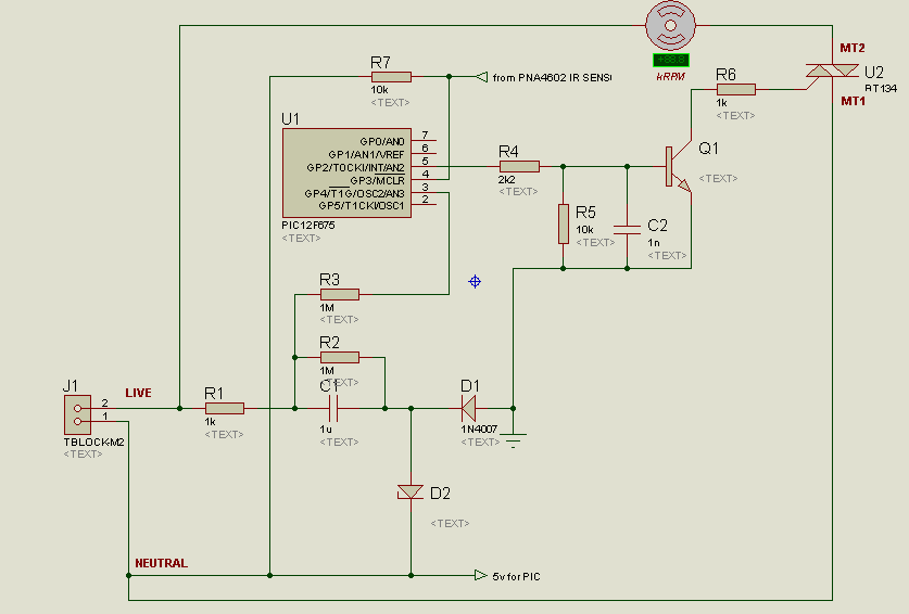
A project is underway to control the speed of an electric fan (220Vac, 60W, 5A max.) automatically using a microcontroller based on certain parameters. The circuit design for controlling the speed of an electric fan involves several key components to...
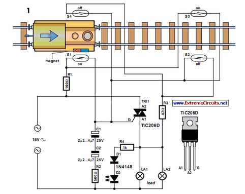
Modern electronics is essential for every large model railroad system, providing solutions to nearly every issue. Although ready-made products are available... Modern model railroad systems rely heavily on advanced electronics to enhance functionality and user experience. These systems often incorporate...
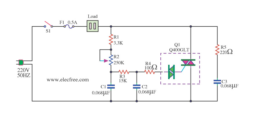
This is a 1200-watt AC power dimmer that utilizes a triac Q4006LT. The 1200-watt AC power dimmer circuit is designed to control the brightness of incandescent lamps and other resistive loads. The core component, the triac Q4006LT, is a semiconductor...
This solid-state relay circuit operates using 120 volts from household mains and should only be constructed by individuals with the necessary knowledge and skills to ensure safety. Failure to do so may result in personal injury or property damage. The...
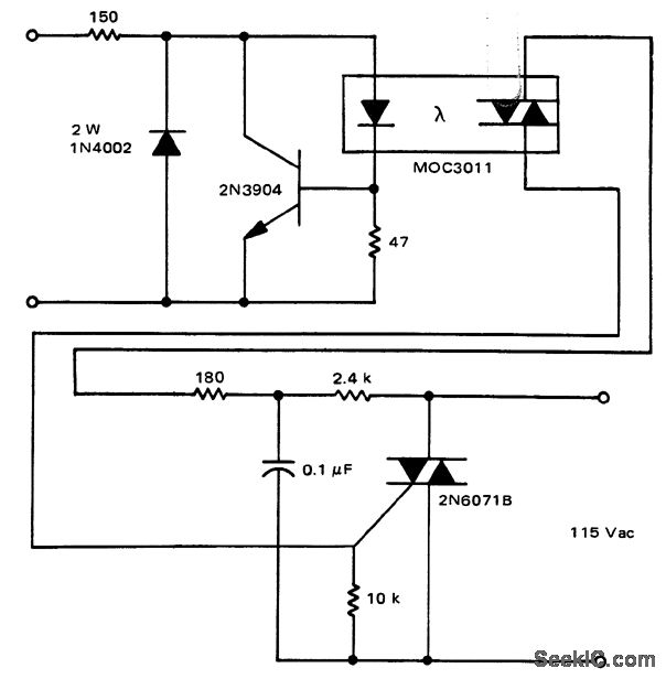
A solid-state relay circuit features an input protection mechanism utilizing the MOC3011 triac driver. The input voltage for the protection circuit can range from 3 to 30 volts DC, as noted by Motorola Semiconductor Products Inc. The solid-state relay (SSR)...
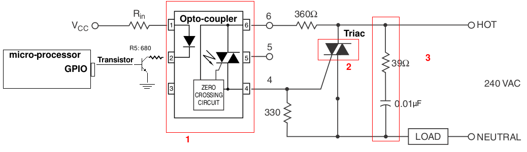
A light-dimming control system is being developed for a 240V heat lamp with a power dissipation of approximately 250W. The objective is to adjust the heat output of the lamp using control from a microprocessor. The development is based...