
Solid State Triac Relay Schematic
The solid-state relay (SSR) circuit serves as an efficient method for controlling high-voltage loads using low-voltage control signals. It provides electrical isolation between the control side and the load side, enhancing safety in applications where high voltages are involved. The SSR typically consists of an opto-isolator to separate the input control signal from the output load circuit, along with a power semiconductor device, such as a triac or a MOSFET, to switch the load on and off.
In this circuit, the control input is connected to a low-voltage signal, which can be derived from a microcontroller or a switch. When the control signal is activated, the opto-isolator is triggered, allowing current to flow through the output stage. This current activates the power semiconductor, enabling it to conduct and thus energize the load connected to the 120-volt mains.
The design should include protective components, such as fuses or circuit breakers, to safeguard against overcurrent conditions. Additionally, heat sinks may be required to dissipate heat generated by the power semiconductor during operation, ensuring reliable performance and longevity of the relay.
Proper consideration of layout and component ratings is crucial to ensure that the circuit can handle the intended load without exceeding voltage and current specifications. It is also advisable to include snubber circuits or other protection mechanisms to mitigate voltage spikes that may occur when the load is switched off, protecting the SSR from potential damage.
In summary, this solid-state relay circuit is a practical solution for controlling AC loads with low-voltage signals while providing isolation and safety. However, it requires careful design and assembly by qualified individuals to prevent hazards associated with high voltage.This solid state relay circuit uses 120 volts household mains and should only be attempted by someone that has the knowledge and skills to safely construct such a project. Otherwise personal injury and or property damage could result. 🔗 External reference
Related Circuits
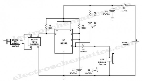
This is an interesting hobby circuit for a crank doorbell. The circuit is built around a 555 timer and a musical piezo buzzer, powered by a 9-volt battery. A single 9-volt PP3/6F22 compact battery is sufficient to power the...
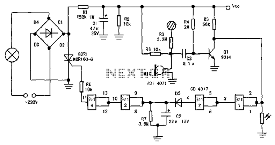
The circuit diagram illustrates a sound, light, and touch-controlled delay self-extinguishing switch. It comprises three main sections: the power circuit, the signal conversion detecting circuit, a delay circuit, and a control circuit. 1. Power Circuit: This section consists of...
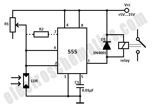
This light-activated relay circuit utilizes the 555 timer integrated circuit (IC) and a light-dependent resistor (LDR) to create a light-sensitive relay suitable for applications such as intruder alarm systems or automatic lamp control at sunset and sunrise. The potentiometer...
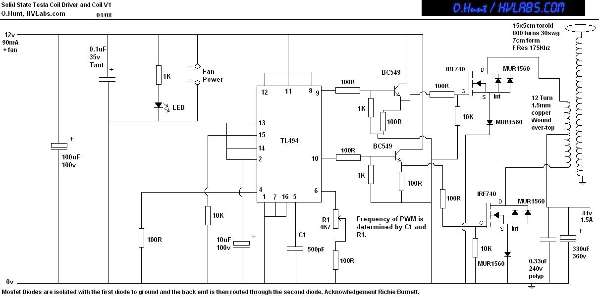
This is a solid-state version of a Tesla coil, replacing the spark gap with MOSFET transistors and utilizing a close-coupled primary coil without capacitors. The method of driving the primary coil varies among designs. After researching various works online,...
The circuit features a two-stage structure with a timing range of approximately 0.5 to 12 seconds, while in a specified configuration, the timing range extends from 1 to 160 seconds. The transformer parameters include an iron core made of...

The circuit depicted in Figure 8 is a low-pass filter utilizing an eight-stage switched-capacitor configuration. The cutoff frequency of the circuit can be adjusted, with a clock frequency that can be modified to 1/100 of the original frequency. A...