
ac TRIAC dimmer circuit design help (resistive load)
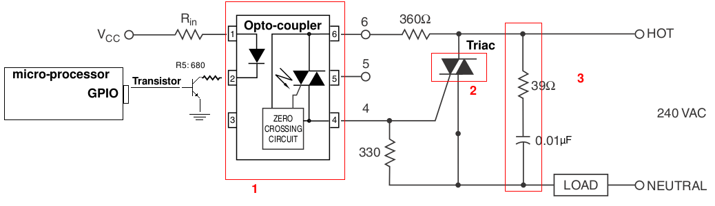
The design of the light-dimming control system will involve several key elements to ensure effective operation and safety. The primary component in this application is a solid-state relay (SSR) or a triac-based dimmer circuit, which will allow for the control of the AC power supplied to the heat lamp. The SSR or triac should be rated for at least 4A to handle the maximum surge current that may occur during the initial switch-on phase, which can be significantly higher than the steady-state current. The selection of the relay must also consider the operational voltage, which in this case is 240V AC.
Incorporating a zero-cross detection circuit can enhance the performance of the dimming control by ensuring that the switching of the relay occurs at the point where the AC voltage crosses zero, thereby minimizing electrical noise and reducing stress on the relay. This is particularly important in applications involving resistive loads like heat lamps, as it extends the lifespan of the switching component.
The microprocessor, based on the 8051 architecture, will control the dimming operation through pulse-width modulation (PWM) or phase control techniques. The PWM signal can be generated by the microprocessor to adjust the average power delivered to the lamp, effectively controlling the heat output. The microprocessor should also be programmed to monitor the current flowing through the heat lamp to prevent exceeding the rated specifications and to ensure safe operation.
To achieve accurate measurements of the current, a current sensing resistor or a Hall effect sensor can be implemented in series with the load. This will provide feedback to the microprocessor, allowing it to adjust the PWM signal dynamically based on the actual current draw of the heat lamp. Additionally, implementing overcurrent protection circuitry, such as a fuse or a circuit breaker rated appropriately for the application, will enhance safety.
Finally, the integration of RF circuitry will allow for remote control and monitoring of the heat lamp's operation, providing flexibility and enhancing user convenience within the wireless sensor network. The system design should also include considerations for heat dissipation from electronic components, ensuring that the overall system remains within safe operating temperatures.Making a light-dimming control system for a 240V heat lamp dissipating around 250W. I need to adjust the heat output on the lamp by control from a microprocessor. I`m developing on an 8051-based SoC with RF circuitry and some sensors and actuators. Basically it`s a node in a wireless sensor network. I`ve left all other components out. I`m mostly a software guy, so I might need some help here. Pardon my lingo and if I raise fundamental questions, I don`t have a lot of experience with this. A max surge-current rating of 4A would leave some overhead I would assume, but I`m not sure how much I need. I am assuming a switch-on from cold could draw a lot of current - should I instrument to be sure I don`t have any data on the heat lamp other than its rated for 250W max.
🔗 External reference
Related Circuits
The automatic toilet flusher is designed to restructure the traditional flushing mechanism, allowing for a single, reliable flush after each use. It features energy-saving capabilities and a long-lasting chip, ensuring ease of use even when disconnected from the power...
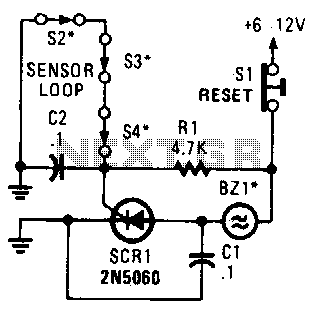
A string of three series-connected, normally closed switches is connected across the gate of a silicon-controlled rectifier (SCR). When one switch opens, the SCR is triggered through resistor R1, activating an alarm. The alarm is designed to be of...

A preferred STK4040xl Fi amplifier circuit exhibits excellent electrical parameters: under specific conditions, the output voltage (Uc) is 43V with a load resistance (RL) of 8 ohms. The circuit is designed to deliver a rated output power of at...

Notebook computer chip power supply circuit, which generates the PWM circuit using MAX8775. The notebook computer chip power supply circuit utilizes the MAX8775 integrated circuit to generate a Pulse Width Modulation (PWM) signal. The MAX8775 is a high-efficiency step-down voltage...
A voltage supply ranging from 6 V to 15 V is required when using a single LED per module. An increase in the number of LEDs necessitates a corresponding increase in the voltage supply, with additional LEDs connected in...
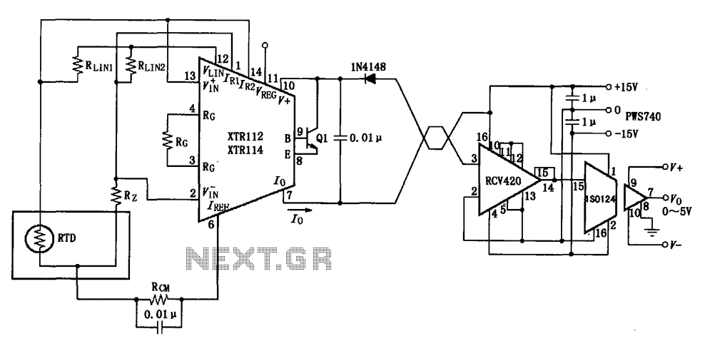
The RTD temperature data collected at the scene is converted into a voltage using the XTR112/114. This voltage is further transformed into a 4 to 20 mA current output, which is then transmitted via a twisted pair. The RCV420...