
wireless motor control through rf

The circuit design integrates several key components for effective operation. The HT12E encoder is responsible for converting parallel data inputs into a serial format suitable for RF transmission. The RF transmitter then modulates this serial data and transmits it wirelessly. Upon reception, the RF receiver demodulates the signal, and the HT12D decoder converts the serial data back into parallel form for further processing. The inverter (74LS04) is crucial for adjusting the logic levels from the decoder to match the requirements of the motor driver IC (L293D). The L293D IC is particularly advantageous because it allows for the control of two DC motors, enabling simultaneous operation in both directions. The H-bridge configuration within the L293D permits efficient control of motor speed and direction through the application of specific logic levels to its input pins. Overall, this RF-controlled DC motor system exemplifies a robust solution for remote motor management, leveraging the benefits of RF communication to enhance operational flexibility and reliability.The way DC motors can be driven by using the controls from a distant place. The controls are transferred from one end to another by employing an RF module. This circuit uses RF module to control DC motors through a motor driver IC L293D. Transmission is enabled by giving a low bit to pin14 (TE, active low) of encoder HT12E. The controls for motor are first sent to HT12E. Pins 10 and 11 (D0-D1) are used to control one motor while pins 12 and 13 (D2-D3) to control another motor. The data signals of encoder HT12E work on negative logic. Therefore a particular signal is sent by giving a low bit to the corresponding data pin of encoder. The parallel signals generated at transmission end are first encoded (into serial format) by HT12E and then transferred through RF transmitter (434 MHz) at a baud rate of around 1-10 kbps. The same signals are acquired by RF receiver after which it is decoded by HT12D. For more details, refer RF remote control. Since the encoder/decoder pair used here works on negative logic, the decoded signals are fed to an inverter (NOT gate) IC 74LS04.
The proper (inverted) signals are then supplied to L293D. L293D contains two inbuilt H-bridge driver circuits to drive two DC motors simultaneously, both in forward and reverse direction. The motor operations of two motors can be controlled by input logic at pins 2 & 7 and pins 10 & 15. Input logic 00 or 11 will stop the corresponding motor. Logic 01 and 10 will rotate it in clockwise and anticlockwise directions, respectively. Thus, depending upon the signals generated at the transmission end, the two motors can be rotated in desired directions.
The RF module, as the name suggests, operates at Radio Frequency. The corresponding frequency range varies between 30 kHz & 300 GHz. In this RF system, the digital data is represented as variations in the amplitude of carrier wave. This kind of modulation is known as Amplitude Shift Keying (ASK). Transmission through RF is better than IR (infrared) because of many reasons. Firstly, signals through RF can travel through larger distances making it suitable for long range applications. Also, while IR mostly operates in line-of-sight mode, RF signals can travel even when there is an obstruction between transmitter & receiver.
Next, RF transmission is more strong and reliable than IR transmission. RF communication uses a specific frequency unlike IR signals which are affected by other IR emitting sources. This RF module comprises of an RF Transmitter and an RF Receiver. The transmitter/receiver (Tx/Rx) pair operates at a frequency of 434 MHz. An RF transmitter receives serial data and transmits it wirelessly through RF through its antenna connected at pin4.
The transmission occurs at the rate of 1Kbps 10Kbps. The transmitted data is received by an RF receiver operating at the same frequency as that of the transmitter. The RF module is often used alongwith a pair of encoder/decoder. The encoder is used for encoding parallel data for transmission feed while reception is decoded by a decoder.
HT12E - HT12D, HT640-HT648, etc. are some commonly used encoder/decoder pair ICs. 🔗 External reference
Related Circuits
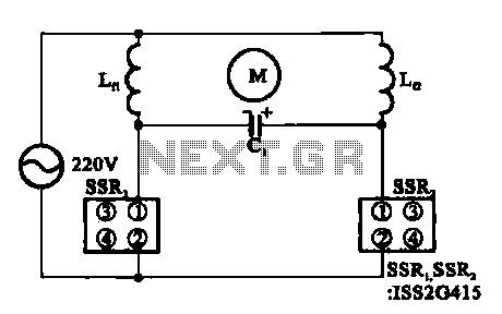
The triac motor drive circuit depicted demonstrates the operation of a TRIAC, which is often referred to as a solid-state relay. Figure (a) illustrates the circuit configuration, while figure (b) presents the connections for the motor coils. The triac motor...
A Nidec TA450DC B35502-35 fan has been installed in a large wooden cabinet housing a computer and other electronics, which generates significant heat. The fan is designed to draw air from the room and exhaust it through openings at...
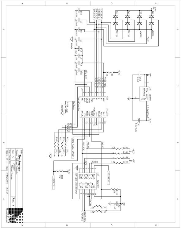
The following are detailed schematics for the QScreen Controller. The QScreen Controller integrates an embedded computer utilizing the 68HC11 microcontroller, along with a touch panel and an LCD (liquid crystal display) graphic user interface (GUI) that is well-suited for...
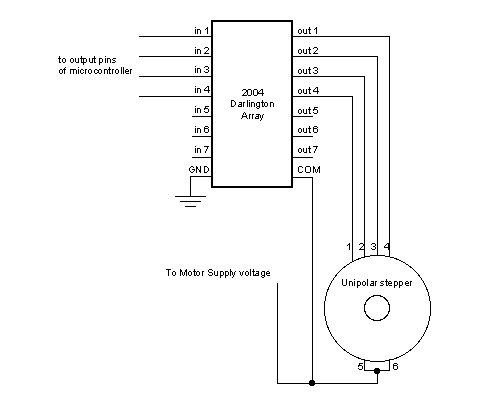
Stepper motors, because of their distinct design, can be operated with a high level of precision without the need for feedback mechanisms. The shaft of a stepper motor, equipped with a series of magnets, is governed by a set...
This page is provided to the domain owner free by Sedo's Domain Parking. Disclaimer: The domain owner and Sedo maintain no relationship with third-party advertisers. References to any specific service or trademark are not controlled by Sedo or the...
For normal use it is necessary to connect the battery when the jumper is connected. Please take care that the transmitter is on and the throttle is set to "power off". More: * switch on the transmitter, throttle to...