
Triac low output problem

The circuit design employs two 3023 optoisolators to provide electrical isolation between the control signals and the high-voltage components, ensuring safety and preventing interference. Each optoisolator is connected to its respective triac, which serves as a switch for the 3-phase contactors. The optoisolators allow for low-voltage control signals from the custom controller IC to manage the higher voltage requirements of the heaters.
The functioning triac circuit demonstrates a stable operation, indicated by the waveform captured in the upper image. In contrast, the malfunctioning triac circuit exhibits a significant drop in voltage immediately after reaching peak positive voltage, suggesting that the triac may not be receiving adequate gate drive current. This behavior could be attributed to a short gate pulse duration, which may not be sufficient to keep the triac in a conductive state throughout the AC cycle.
To address this issue, it is recommended to analyze the gate pulse duration and ensure it is extended to cover a substantial portion of the AC cycle. A pulse duration of approximately 90% of the AC waveform could help maintain triac conduction, especially when driving inductive loads such as coils.
The PSIM simulation results indicate that adjusting the control duty cycle can significantly impact the performance of the triac. With a duty cycle of 0.7, the output waveform shows undesirable characteristics, while increasing the duty cycle to 0.8 allows for a complete sinusoidal waveform, indicating that the load receives the necessary power for proper operation.
Further investigation into the stability of the logic input to the optoisolator is necessary, as any fluctuations in the 5 VDC supply might affect the operation of the triac without influencing the overall logic circuit. Ensuring a stable power supply and checking the integrity of the components involved in generating the gate signal are critical steps in troubleshooting the circuit.
In summary, the successful operation of the circuit hinges on the careful management of gate pulse duration, duty cycle adjustments, and the stability of the control signals. Understanding the interplay between these factors will be essential for resolving the issues observed with the non-functioning triac circuit.The circuit is two separate 3023 optoisolators driving two separate triacs, each one powering a large 3-phase contactor. One contactor is engaging fine. The other one is rattling badly because it isn`t getting full power to pull in. The top photo shows trace from the good triac circuit, working fine. Bottom photo shows the bad one. It looks like t he triac is dropping out right after hitting peak positive voltage. Thanks for any help. I`m a first time poster who is in over his head on a repair - really more of a mechanical guy than an electrical expert. (I`d be happy to trade mechanical advice!) The triac should only turn off when the current passes through zero.
Since you are driving a coil, maybe the current passes through zero where you see the voltage drop. To be sure you would need to measure load current too (on a scope). As you can see from the attachment I can simulate something very much like the result you are seeing. The problem arises from too short a gate pulse. If you are applying a pulse (y/n ) to the triac gate you may need to make it longer - say 90% of the AC cycle in duration.
As you can see from the attachment I can simulate something very much like the result you are seeing. The problem arises from too short a gate pulse. If you are applying a pulse (y/n ) to the triac gate you may need to make it longer - say 90% of the AC cycle in duration.
The load voltage. The PSIM schematic used is attached. I guessed the circuit values. With a control duty cycle of 0. 7 I obtain the waveform indicated earlier. With the duty cycle increased to 0. 8 the problem vanishes and the load has the full sinusoid imposed. One would have to know the actual circuit parameters to correctly advise the OP. The load voltage. The PSIM schematic used is attached. I guessed the circuit values. With a control duty cycle of 0. 7 I obtain the waveform indicated earlier. With the duty cycle increased to 0. 8 the problem vanishes and the load has the full sinusoid imposed. One would have to know the actual circuit parameters to correctly advise the OP. Thanks for the help. The logic input is driven from a custom controller IC. Its outputs control two 120VAC heaters. The controller is reading voltage across two thermistors, reading some jumpers to determine the temperature setpoint, and then driving the optoisolator. I didn`t think to check the stability of the logic input to the optoisolator. I don`t know why the controller would be pulsing that line, but I`ll check it. Could ripple in the 5 VDC supply cause enough variation to throw off the triac but not the rest of the logic The identical circuit for the other contactor works fine.
Thanks for the help. The logic input is driven from a custom controller IC. Its outputs control two 120VAC heaters. The controller is reading voltage across two thermistors, reading some jumpers to determine the temperature setpoint, and then driving the optoisolator. I didn`t think to check the stability of the logic input to the optoisolator. I don`t know why the controller would be pulsing that line, but I`ll check it. Could ripple in the 5 VDC supply cause enough variation to throw off the triac but not the rest of the logic The identical circuit for the other contactor works fine.
The values of the components that determine the photodiode current and gate signal to the triac may just be at the limit. This is why one circuit can work and the other not. It doesn`t need to be necessarily a problem with a defective component. It depends at what point in the AC voltage cycle the triac is turned on as to whether you have a transient DC offset.
Do you recollect your circuit theory transient analysis studies from the old days It depends at what point in the AC voltage cycle the triac is turned on as to whether you have a transient DC offset. Do you recollect your circuit theory transient analysis studies from the old days 🔗 External reference
Related Circuits
This circuit utilizes an LM11 operational amplifier configured as a voltage follower with an input resistance of 1 GΩ, constructed using standard resistor values. When the input is left disconnected, the input offset voltage is amplified by the same...
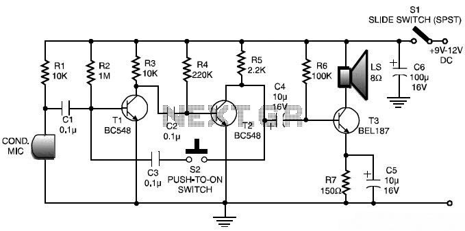
This is a low-cost and simple intercom circuit design. Some intercom circuits are built using integrated circuits. The circuit described here utilizes three readily available transistors that can be easily found in electronic stores. Even a novice can assemble...
Stationary - MOPLL & Silicon Tuner TUA6020 2 Band TV Tuner Mixer-Oscillator-PLL with balanced IF-Amplifier. The TUA6020 device integrates a digitally programmable Phase Locked Loop (PLL) with a mixer-oscillator block that includes two balanced mixers and oscillators suitable for...
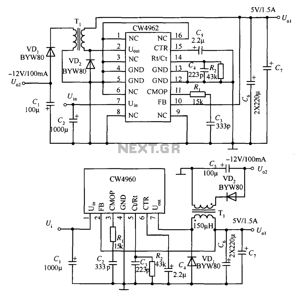
The circuit described is a stabilized power supply utilizing the CW4962 and CW4960 components, providing +5V at 1.5A and -12V at 100mA. The +5V output serves as the main power supply. The output circuit employs a transformer rather than...
%2BCircuit%2Bdiagram%2Busing%2BCD4047%2Band%2BIRFZ44%2Bpower%2BMOSFET.png)
This simple low-power DC to AC inverter circuit converts 12V DC to either 230V or 110V AC. By making simple modifications, it is also possible to convert 6V DC to 230V AC or 110V AC. This inverter can be...

Building a signal generator is an essential project for any analog DIY enthusiast. While already possessing a bench signal generator, the intention was to create a compact, battery-powered device for quickly testing new effect designs. An enclosure from a...