
Triac mains light dimmer

The schematic describes a conventional light dimmer circuit designed for controlling the brightness of incandescent lamps. The circuit incorporates several key components: a potentiometer, resistors, a DIAC, a TRIAC, and capacitors, all of which work together to modulate the power delivered to the lamp.
The heart of the dimmer is the TRIAC (T2), such as the TIC226D, which is responsible for switching the lamp on and off at a controlled rate. The TRIAC is triggered by the DIAC (T1), which is typically an ER900 or DB3. The DIAC only conducts when the voltage across it exceeds a certain threshold, allowing for a sudden surge of current to trigger the TRIAC. This feature is crucial for controlling the phase angle of the AC waveform, thus dimming the light.
The potentiometer (P1), rated at 500 kΩ, allows for user adjustment of the brightness level. By varying the resistance, the phase angle at which the TRIAC is triggered can be changed, thus controlling the amount of power delivered to the lamp.
The resistor (R1) with a value of 470 ohms and a power rating of 1/2W serves to limit the current flowing into the gate of the TRIAC, ensuring safe operation and preventing damage to the components.
Capacitors C1, C2, and C3, each rated at 100nF and 400V MKT or class X2, are used for snubber circuit applications to suppress voltage spikes and prevent electromagnetic interference (EMI). The dual dimmer suppressor (L1) works in conjunction with these capacitors to further reduce noise in the circuit, providing a stable operation.
When implementing this circuit, it is essential to consider the maximum current rating of the TRIAC in relation to the lamp's power rating to ensure reliable performance. Proper component selection, particularly for the capacitors and TRIAC, is critical to the overall functionality and safety of the dimmer circuit.This is the schematic of the conventional light dimmer. L1 and C2, C3 form the lichtnetontstoring. In this circuit meets almost every TRIAC as a TIC226D. For C1, C2 and C3 good capacitors (MKT example) with a minimum operating voltage of 400V. Think with the lamp power to the maximum current that the triac can handle. P1 = 500 k ohm potentiometer lin R1 = 470 ohm 1/2W T1 = ER900 or DIAC DB3 T2 = TRIAC eg TIC226D L1 = Dual Dimmer suppressor C1 .. C3 = 100nF 400V MKT or class X2 🔗 External reference
Related Circuits
This simple and inexpensive circuit built around a popular CMOS hex inverter IC CD4069UB offers four sequential switching outputs that may be used to control 200 LEDs (50 LEDs per channel), driven directly from mains supply. Input supply of...
Hobby servos convert DMX signals into mechanical motion. Typically, hobby servos require a pulse with a variable width ranging from 1 to 2 milliseconds, with 1.5 milliseconds representing the center position. The schematic below illustrates a simple voltage-to-pulse-width circuit....

This circuit is capable of generating up to 1 W of audio power to drive a speaker or horn. When the CDS cell is exposed to light, its resistance decreases, activating NOR gate (a). This activation causes gates (a)...
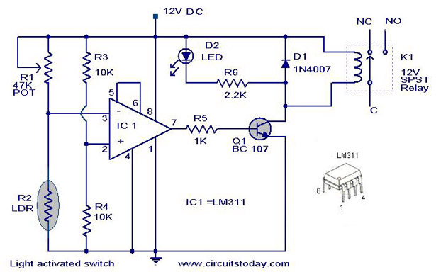
The following circuit illustrates a Light Activated Switch Circuit Diagram. This circuit is based on the LM311 integrated circuit, which functions as a voltage comparator. The Light Activated Switch Circuit utilizes the LM311 voltage comparator to control the switching of...
The circuit is a battery charging system powered by Q2, Q6, R8, and D10, which provides constant current to charge the battery. When an external power supply is present, the charging current flows through R8 and D10 to charge...
This little circuit can be used to dim lights up to about 350 watts. It uses a simple, standard TRIAC circuit that, in my experience, generates very little heat. Please note that this circuit cannot be used with fluorescent...