
Triangle-square wave VCO

The voltage-controlled oscillator (VCO) circuit is designed to generate two distinct waveforms: a triangle wave and a square wave, both of which are buffered to ensure signal integrity and drive capability. The frequency of the generated waveforms is primarily determined by the output voltage swing of the Schmitt trigger, designated as IC2 in the schematic. The Schmitt trigger's output provides a stable reference point that influences the oscillation frequency, allowing for precise control over the waveform characteristics.
To optimize the performance of the VCO, it is recommended to replace the transistor Q1 with a switching field-effect transistor (FET). This substitution is advantageous due to the FET's high input impedance and rapid switching capabilities, which significantly enhance the overall response time of the circuit. The use of a switching FET can reduce power consumption and improve linearity in the output waveforms, making it suitable for applications requiring high fidelity and fast signal transitions.
Furthermore, incorporating fast FET operational amplifiers into the design will further improve the high-frequency performance of the circuit. These operational amplifiers are characterized by their ability to handle rapid changes in signal levels without introducing significant distortion or delay. Their implementation will ensure that the VCO maintains its performance across a wide range of frequencies, making it ideal for applications in signal processing, modulation, and frequency generation.
Overall, the combination of a Schmitt trigger, a switching FET, and fast FET op-amps creates a robust VCO design capable of delivering high-quality waveforms with precise frequency control and enhanced performance characteristics.The VCO has two buffered outputs; a triangle wave and a square wave. Frequency is dependent on the output voltage swing of the Schmitt trigger, IC2. Superior performance can be obtained by replacing Ql with a switching FET. Fast FET op amps will improve high frequency performance.
Related Circuits
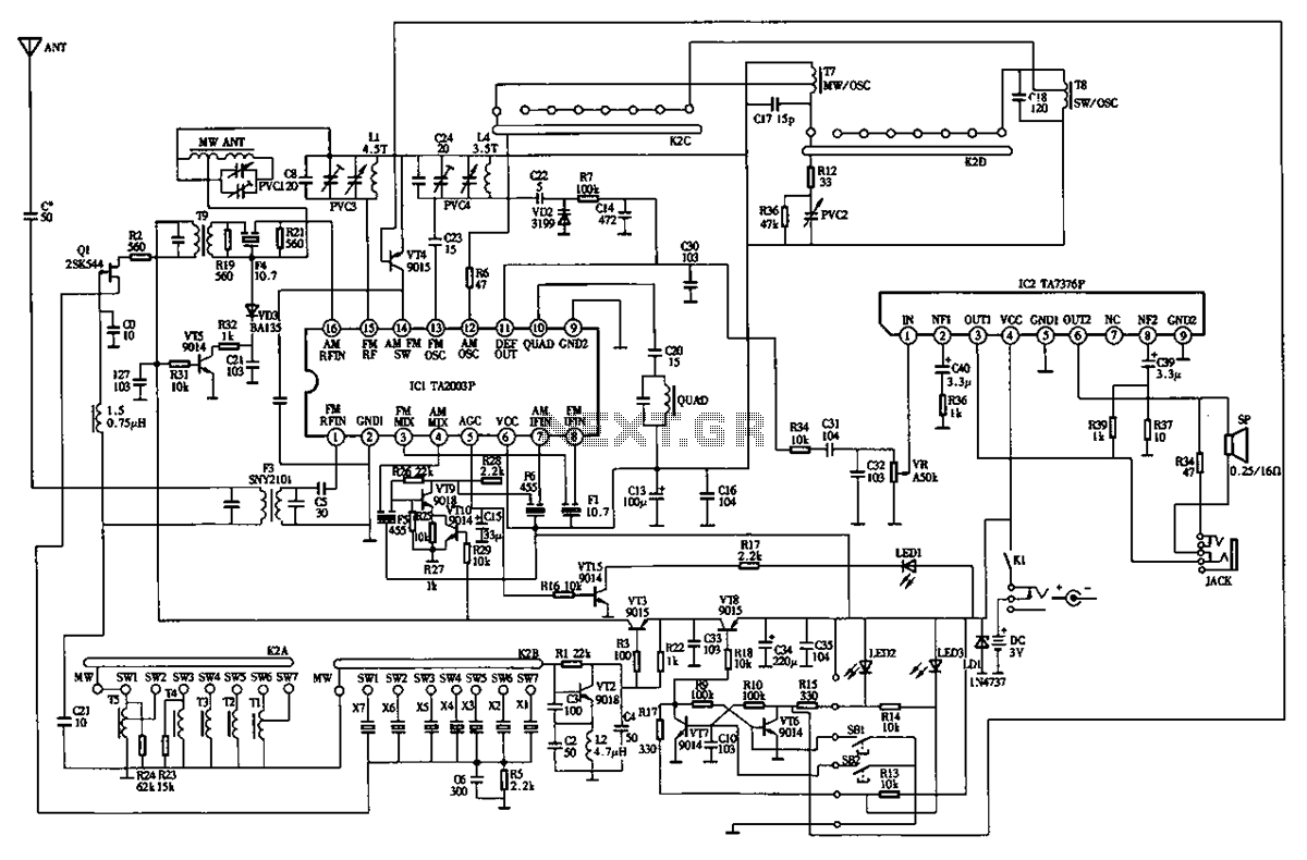
The circuit diagram for the Desheng 89701 type radio, a compact shortwave receiver, is provided below. The Desheng 89701 is designed for shortwave reception, making it suitable for capturing a variety of radio frequencies across the shortwave band. The circuit...
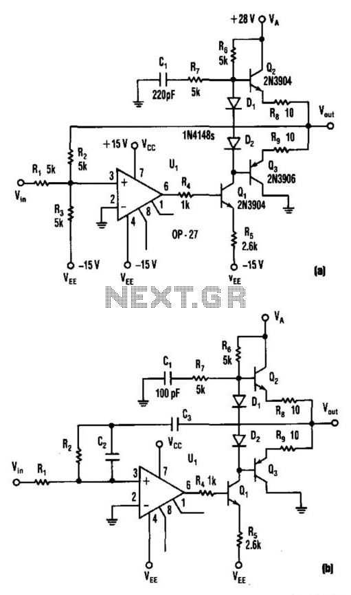
This circuit produces a 5 to 25 V output to drive a voltage-controlled oscillator (VCO) from a standard ±15 V supply system. Resistor R7 and capacitor C1 provide frequency compensation. Transistors Q1 through Q3 form an inverting amplifier with...
This circuit generates a stable 1 kHz sine wave using the inverted Wien bridge configuration (C1-R3 & C2-R4). It features a variable output, low distortion, and low output impedance to ensure good overload capability. A small filament lamp provides...
Achieving the appropriate amplifier loop gain is a significant challenge in generating a low distortion, constant amplitude sine wave. Nevertheless, this issue can be addressed with... Amplifier loop gain is a critical parameter in the design of audio and signal...

This design circuit functions as a sine wave oscillator, providing both sine and square wave outputs across a frequency range from below 20 Hz to above 20 KHz. The oscillation frequency can be easily adjusted by varying a single...
The construction of a low-frequency harmonic signal generator is essential for debugging and measuring audio amplifiers and other circuits. The low-frequency harmonic signal generator is a critical tool designed to produce stable and precise low-frequency signals, which are crucial for...