
Trickle charger circuit schematics
The trickle charger circuit is designed to provide a reliable and safe method for charging nickel-cadmium batteries used in flashlights. The charging mechanism employs a constant current approach to ensure that the battery is charged slowly, which is essential for extending battery life and ensuring safety during the charging process. The use of a diode rectifier allows for the conversion of AC voltage from the mains supply into a usable DC voltage for charging the batteries.
The inclusion of capacitor C1 is critical, as it not only smooths out the pulsating current but also determines the charging current based on its capacitance value. With a capacitance of 0.47μF, the circuit is optimized to deliver a steady current of approximately 30mA, which is ideal for trickle charging. The charging indicator, represented by the ED network and LED, provides a visual cue that charging is in progress, enhancing user convenience.
The electrolytic capacitor C2 plays an important role in stabilizing the LED indication, ensuring that the light remains steady during operation. This is particularly useful in applications where the charging status needs to be monitored easily. Resistor R1, as the bleed resistor, prevents potential overcharging by discharging C1 when the circuit is not in use.
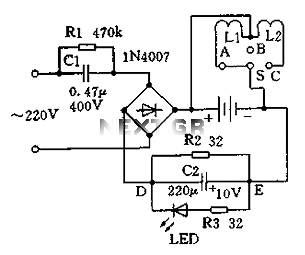
The switch S facilitates user interaction with the circuit, allowing for easy selection between charging and lighting modes. The design ensures that the user can quickly switch between using the flashlight and charging the batteries without the need for complex setups. However, it is crucial to note that because the circuit is not isolated from the power supply, safety precautions must be taken to avoid electrical hazards, making it unsuitable for homemade versions. Overall, this trickle charger design emphasizes safety, efficiency, and user-friendliness, making it a practical solution for charging nickel-cadmium batteries in flashlight applications. Charging the battery using a slow manner (charging current, long time) is the most economical and safest way. Design the trickle charger should grasp two points: First, the use of constant current charging; second, can be applied appropriate form of protection circuit. The following is a trickle charger to charge the battery for different purposes. Nickel-cadmium battery charger with flashlight A common market with a nickel-cadmium battery flashlight rectangular shape, all-plastic shell, one end of the head with two light bulbs, and the other end of the head with the power plug can be plugged directly into an electrical outlet to charge. Rectangular housing and is equipped with a charger circuit 2 5 nickel-cadmium batteries. Charger circuit is shown, which consists of two parts, the charging and lighting circuit. Working process are summarized as follows: ~ 220V voltage through capacitor C1 after limiting by diode rectifier, rectified pulsating current through the battery and ED network reach to charge the battery and charging indication purposes.
Because the capacitor capacitance [1/(wC1)] much larger than the charging circuit impedance loop current (charging current) is mainly determined by the value of C1, so that part of constant current charging mode, the circuit capacitor C1 is 0.47uF (capacitance about 6.8k ohms), the battery charge current is about 30mA. ED network is charging indicator circuit, R2 diversion effect, the flow through the LED current of less than 10mA.
Electrolytic capacitors C2 play the role of energy storage, the LED light indication is stable. Resistor R1 is C1 bleed resistor. Switch S, the lamp L1, L2 and a battery lighting circuits. S is a single-pole three-throw switch, S A throw point, bright lights L1; S throw point C, bright light L2; throw point B, L1, L2 is off, the location is charging switch S should be at. The circuit and power can not be isolated, for security reasons, not homemade.
Related Circuits
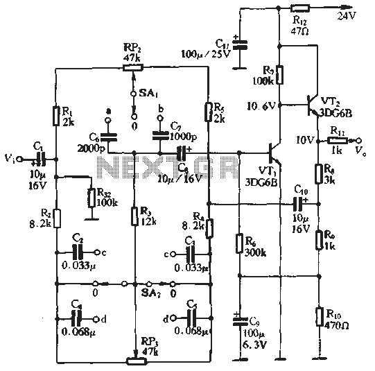
An attenuation switch is utilized to modify the pitch of a feedback control circuit's transition frequency, specifically for two treble controls. RP3 is designated for bass control, while SA1 and SA2 are employed to adjust the high bass control...
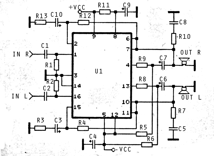
The audio amplifier circuit is highly suitable for home use, particularly with subwoofer or woofer speakers. Commonly referred to as a home amplifier, these audio amplifiers are based on integrated circuits (ICs), specifically the STK series, which includes models...
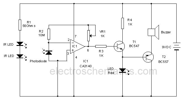
This circuit utilizes invisible infrared light to detect the movement of individuals through a doorway. A brief beep will be emitted when the infrared beam is interrupted. The infrared movement detection circuit employs an infrared LED and a photodiode or...
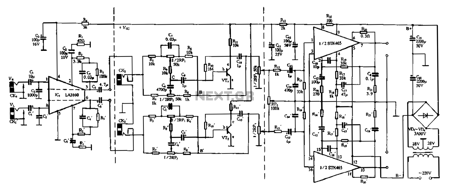
The 50W is a two-channel amplifier featuring a preamplifier and tone control based on the LA3160 integrated circuit. Its external components include the input preamplifier, with C1 serving as the input coupling capacitor. The circuit incorporates a high-frequency bypass...
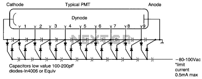
A Cockcroft-Walton voltage multiplier provides the necessary stepped voltage for the dynodes of the photomultiplier tube (PMT) without the use of a power-wasting voltage-divider resistor, which is typically employed in traditional configurations. The Cockcroft-Walton voltage multiplier is a type of DC-DC...
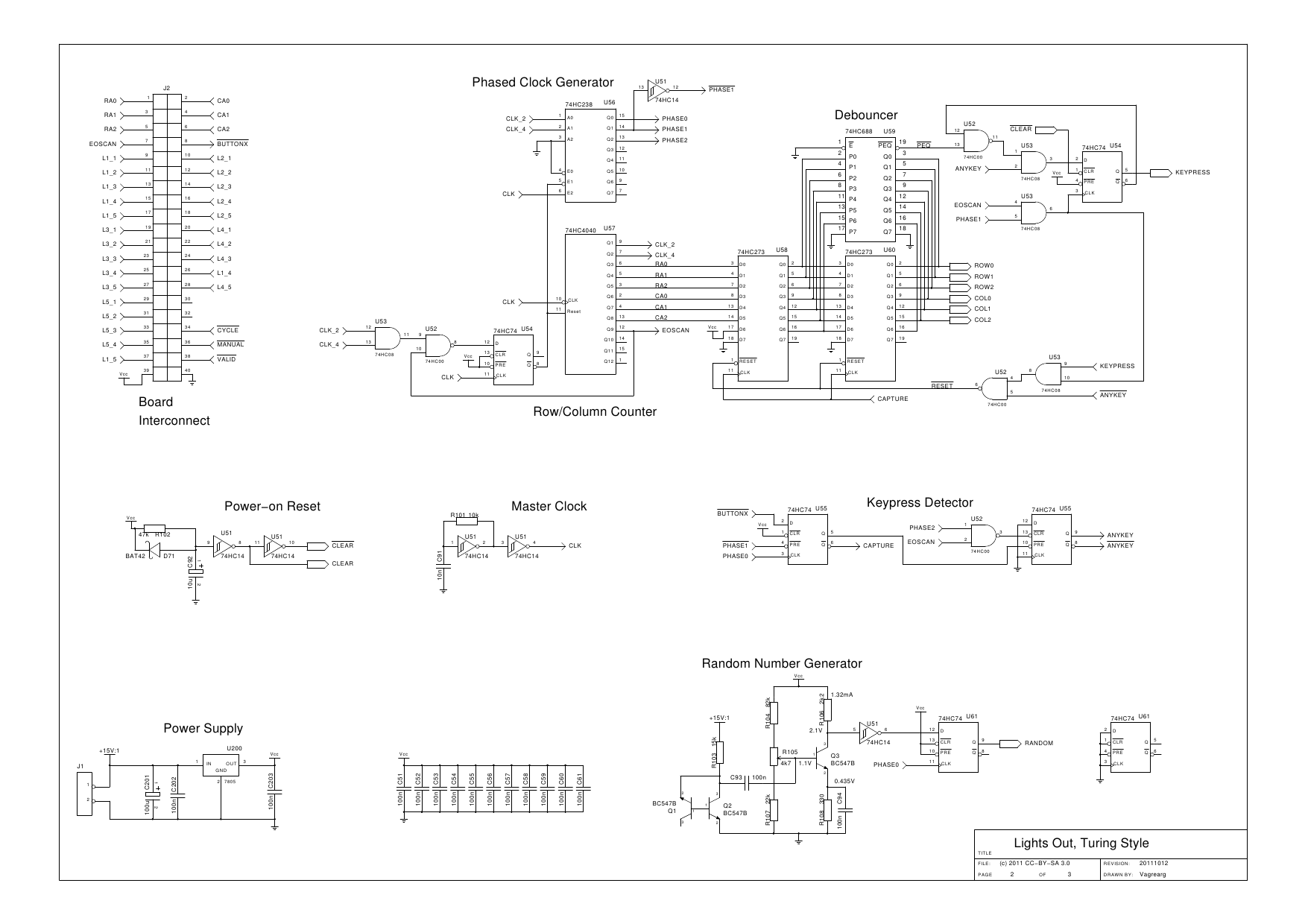
The design is based on the previous analysis of calculating the game in a circular shift register. While designing, it was realized that small extensions to the design would enable additional gameplay features, such as replay and manual input....
Warning: include(partials/cookie-banner.php): Failed to open stream: Permission denied in /var/www/html/nextgr/view-circuit.php on line 713
Warning: include(): Failed opening 'partials/cookie-banner.php' for inclusion (include_path='.:/usr/share/php') in /var/www/html/nextgr/view-circuit.php on line 713