
TrikiBoard 8052
It is crucial to instruct the PCB manufacturer to drill 0.8mm holes for the L298 and 7805 chips; if the holes are not sufficiently large, the chips will not fit, rendering the PCB unusable. Additionally, R1 and C3 are positioned beneath the 89C52 chip, so these components should be soldered first. C3 should be soldered in a manner that allows it to be bent under the chip (leaving a small pin length above the surface for bending) or soldered on the opposite side, ensuring correct polarity. The standard soldering procedure should be followed: solder IC sockets first, then components with the lowest profile, concluding with capacitors, connectors, and the 7805. RN1 and RN2 are single-in-line resistor packs (SIP resistors) that should utilize 4.7k ohm SIPs with 8+1 pins. The common pin, indicated by a dot, connects to the Vcc (+5V) track. Care must be taken to avoid contact between the metal body of the crystal (Q1) and the surface of the PCB if it is not coated with green paint.
The TrikiBoard Version 1.0 is a straightforward board designed to provide a foundation for Yantriki Level 3 participants requiring a microcontroller board for robot control. It serves as a base for EDL beginners who need a serial link to a PC or a memory interface with the microcontroller to evaluate initial project designs.
Power Supply: An 8 to 12 volts supply should be applied through connector K1, which will power the motors connected to the board. The onboard 7805 chip will regulate this voltage down to 5 volts for the microcontroller. If the 7805 or L298D chips overheat, it is necessary to attach a heatsink to them, as commonly available 7805 chips typically require one. The board is capable of driving two DC motors, which may be wheel-drive motors. The L298D chip functions as a dual H-bridge, with motor direction controlled by four port pins. Motor speeds can be modulated through Pulse Width Modulation (PWM) signals generated by software on these pins. In alternative mechatronic applications, a bipolar stepper motor (typically a 4-wire type) can also be operated by connecting its two windings to K1 and K2 instead of the two DC motors. Additionally, the two onboard LEDs associated with each motor can be used for debugging purposes, with the red LED indicating one motor's direction.IC4, MAX232, is used to connect to the PC by serial port. This connection is useful for debugging and controlling the robot by issuing the command through the keyboard of the PC. Though in real autonomous run of the robot, this connection would be taken off. Either give the Gerber files to your PCB maker. (you can email the Gerber files directly to Image & co. , and call them on 28347898. They will make the "films or photoplots" of your pcb, which you`ll give to any PCB maker. ) Get the Silkscreen and printing of labels also done on the PCB if you can spend more. (Approx cost of photoplots with legends Rs. 400-450 at Image). Or print the Top and Bottom layer PDF files on a 1200 dpi laser printer, and give the printout to your PCB Film maker or PCB maker directly. I do not recommend this method as the print quality may not be good, and tracks may get shorted. But this is the last resort usually of the Non-Metro residents. Getting the Film made from a printout (the second method above) is usually less expensive but the quality may not be proper.
Your Film-maker will tell you if he can make it from the printout you`ll give to him after looking at it. (approx cost is 25paise/cmsq). Getting the Film made from the Gerber File is more expensive, but the quality is best. It would be better if many friends share a common film`s cost. (In IIT, one of the Yantriki coordinators may get many PCBs made in bunch after finding out the demand, as was done a few years ago).
IITan`s can also try getting their complete PCB done in the PCB facility of EE dept for free. But that pcb would not have component names printed on it. Moreover the dept. facility may not allow too many PCBs of the same type because the tool there is much more expensive in its running cost. IMPORTANT: Tell the PCB maker to drill, 0. 8mm holes for the L298 & 7805 chip. If the holes are not big for these 2 chips, the chip wont go in the PCB and whole PCB would be useless.
IMPORTANT: NOTE THAT R1 and C3 are UNDER the 89c52 chip. Hence solder these first among all. Solder C3 such that it can be bent under the chip (leave little pin length above the surface to allow bending) Or solder it on the opposite side (Take care of the polarity of C3). Then follow the usual soldering procedure: Solder IC Sockets first, and the components with lowest height first.
Thus capacitors, connectors and 7805 go to board last. RN1 & RN2 are Single-in-Line Resistor packs (called SIP resistors in market). Use 4K7 sips, with 8+1 pins. The common pin, denoted by a dot, goes to Vcc (+5v) track. Note that there are tracks on top layer under the Crystal Q1. Hence do not touch the metal body of the crystal to the surface if the PCB is not green painted. As mentioned earlier, TrikiBoard Version 1. 0 is very simple board just to give a head start to Yantriki Level 3 participants who need a Microcontroller Board to control their robots, and it forms a base for EDL Beginners if all they need is a Serial Link to PC or Memory interface to mcu to check their initial project designs. Power Supply: Apply 8 to 12 volts through the connecter K1. This Battery voltage shall be used to drive the motors by the board. The 7805 chip on-board shall produce 5 volts for the microcontroller. If the 7805 or L298D gets heated too much on your board, add a Heatsink to these chips. Commonly available 7805 would require a heatsink. The board can drive 2 DC Motors (which maybe wheel-drive motors). The chip L298D is Dual H-Bridge chip. The motor directions are controlled by the 4 port pins as follows Speeds of the Motors can be controlled by generating a PWM on these Port pins by software.
In other mechatronic applications, a Bi-polar stepper motor (usually 4-wire type) can also be controlled if its 2 windings are connected to K1 & K2 instead of 2 dc-motors. The 2 LEDs associated with each Motor, on-board, can be used for debugging. Red Led would signify one motor direct 🔗 External reference
Related Circuits
The ADUC845 MicroConverter is a fully integrated dual 24-bit, multi-channel Sigma Delta ADC and flash microcontroller on a single chip. This device is a multi-channel extension of Analog Devices' popular ADuC844 and ADuC846 MicroConverter family and is optimized for...
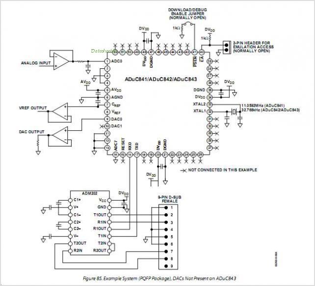
The ADUC841, ADUC842, and ADUC843 are complete smart transducer front ends that integrate a high-performance self-calibrating multichannel ADC, a dual DAC, and an optimized single-cycle 20 MHz 8-bit MCU (compatible with the 8051 instruction set) on a single chip....

Personal safes are innovative locking storage solutions that open with a simple touch of a finger. These devices are designed as secure storage options for medications, jewelry, firearms, documents, and other valuable or potentially hazardous items. They employ fingerprint...
The ADUC832 MicroConverter is a fully integrated 12-bit data acquisition system-on-a-chip. Like all of Analog Devices' MicroConverter products, it features precision A/D and D/A conversion along with a Flash Microcontroller on a single chip. The ADUC832 is completely hardware...
The ADUC816 is a complete smart transducer front-end that integrates two high-resolution sigma-delta ADCs, an 8-bit microcontroller unit (MCU), and program/data Flash EEPROM memory on a single chip. This low-power device accepts low-level signals directly from a transducer. The...
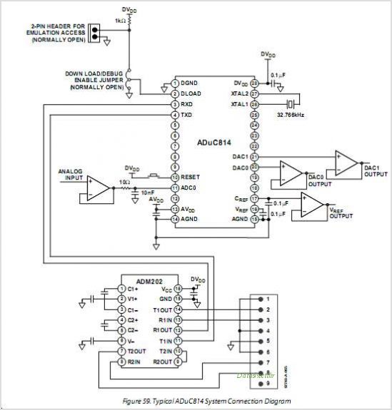
The ADUC814 MicroConverter is a fully integrated 12-bit data acquisition system-on-a-chip. Like all of ADI's MicroConverter products, it features precision A/D and D/A conversion along with a Flash Microcontroller on a single chip. The ADUC814 MicroConverter is designed to streamline...