
Trimless IF VCO: Part 2: New ICs Simplify Implementation
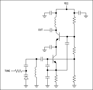
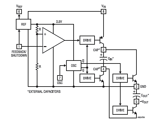
In conventional IF VCO designs, the oscillator core and output buffer stage are typically constructed using discrete transistors, resistors, capacitors, and inductors. The tank circuit is composed of a frequency-setting inductor, varactors, coupling capacitors, and feedback capacitors. The output stage employs reactive elements to match the output impedance to a specific load. To achieve a successful design, component values must not only establish the desired nominal oscillation frequency but also ensure an adequate tuning range, proper biasing, reliable startup under all conditions, and optimal output-stage performance.
Design challenges can arise even with a well-executed initial design due to trade-offs among current consumption, startup margin, frequency tuning range, and phase noise. A significant drawback of discrete IF VCO designs is the extensive PCB area they require, necessitating careful optimization of layout to fit within dimensions of 6 mm x 10 mm. Additionally, PCB layout critically influences VCO performance and design accuracy, as parasitic capacitances and inductances can affect oscillation frequency and must be accounted for in the oscillator implementation. These parasitic elements can cause undesirable shifts in the nominal oscillation frequency, leading to increased design centering errors and necessitating a broader tuning range to accommodate these discrepancies.
The MAX2605-MAX2609 IF VCO family presents a superior alternative, specifically engineered for low-power, fixed, and single-frequency portable wireless applications with IF frequencies ranging from 45 MHz to 650 MHz. Most of the necessary circuitry is integrated on-chip, with only the tank inductor (responsible for setting the oscillation frequency) required as an external component. By selecting an appropriate external inductance value, the IC guarantees that a voltage level within the tuning range (+0.4 VDC to +2.4 VDC) will correspond to the desired frequency. The tuning-voltage input of the IC can be directly driven from the output of a loop filter following a phase-locked loop (PLL).
The MAX2605-MAX2609 ICs operate within supply voltages of +2.7 VDC to +5.5 VDC without necessitating special regulation for proper functionality. Each IC is housed in a compact 6-pin plastic SOT23 package. The MAX2605 model tunes from 45 MHz to 70 MHz, achieving -117 dBc/Hz phase noise at a 100 kHz offset from the carrier. The subsequent devices in the family offer tuning ranges of 70 MHz to 150 MHz with -112 dBc/Hz phase noise (MAX2606), 150 MHz to 300 MHz with -107 dBc/Hz (MAX2607), 300 MHz to 500 MHz with -100 dBc/Hz (MAX2608), and 500 MHz to 650 MHz with -93 dBc/Hz (MAX2609).
The frequency tuning range, biasing, startup, and other oscillator characteristics are all managed internally within the IC, alleviating the typical design complexities associated with VCO development. An integrated varactor and capacitors further streamline IF VCO design by removing the need for external tuning components. A graph illustrating the relationship between inductance and oscillation frequency is provided in the MAX2605-MAX2609 data sheet, which facilitates the selection of an appropriate external inductor. The MAX2605 family offers significant advantages for RF designers, enabling the efficient creation of VCOs.Presents a family of IF voltage-controlled oscillators (VCOs) to cover the frequency range from 45MHz to 650MHz. The ICs are in 6-pin SOT23 packages. Phase noise is -100dBc/Hz for the MAX2608 at 300MHz to 500MHz. An off-chip inductor sets the operating frequency. The output stage can be matched with resistors or lossless techniques. Desig ning a VCO for use with a fixed intermediate frequency (IF) can be daunting. Fortunately, VCO ICs from Maxim (MAX2605-MAX2609) can simplify the task. Compared to conventional discrete-device VCOs, the Maxim parts cost less and require less PC board space. In a traditional IF VCO design, the oscillator core and the output buffer stage are formed by discrete transistors, resistors, capacitors, and inductors (Figure 1).
The tank is built from a networkconsisting of the frequency-setting inductor, varactors, coupling capacitors, and feedback capacitors. The output stage uses reactive elements to match the output impedance to a particular load impedance.
To ensure a successful design, the component values not only must establish a desired nominal oscillation frequency, but they must also guarantee an adequate tuning range, proper biasing, oscillator startup under all conditions, and proper output-stage performance. Problems can occur even with a good first-order design because of the trade-off that exists among current consumption, startup margin, frequency tuning range, and phase noise.
A major disadvantage of discrete IF VCO designs is the amount of PC board area required. Much effort must be expended in optimizing the layout to below 6mm x 10mm. Furthermore, the PC board layout has a critical effect on the VCO`s performance and design accuracy. The layout contains parasitic capacitances and inductances that affect the oscillation frequency and must therefore be taken into account to implement the oscillator properly. Parasitic elements often bring about an undesired shift in the nominal oscillation frequency, which causes greater design-centering errors and ultimately forces a need for greater tuning range to account for those errors.
The MAX2605-MAX2609 IF VCO family offers a better alternative. These five ICs are designed for low-power, fixed- and single-frequency, portable wireless applications with IF frequencies in the 45MHz to 650MHz range. Much of the required circuitry is included on-chip; only the tank inductor (which establishes the oscillation frequency) is external.
Once you choose the correct external inductance value, the IC guarantees that some level within the tuning-voltage range (+0. 4VDC to +2. 4VDC) will tune in the corresponding frequency. The IC`s tuning-voltage input can be driven directly from the loop-filter output following a phase-locked loop ( PLL ).
MAX2605-MAX2609 ICs are designed for supply voltages in the +2. 7VDC to +5. 5VDC range, and the supply voltage connection does not require special regulation for proper operation. Each IC comes in a tiny, 6-pin, plastic SOT23 package (Figure 2). The MAX2605 tunes from 45MHz to 70MHz, with -117dBc/Hz phase noise at 100kHz from the carrier. For the other devices, these parameters are 70MHz to 150MHz tuning with -112dBc/Hz phase noise at 100kHz from the carrier (MAX2606), 150MHz to 300MHz with -107dBc/Hz (MAX2607), 300MHz to 500MHz with -100dBc/Hz (MAX2608), and 500MHz to 650MHz with -93dBc/Hz (MAX2609).
The frequency tuning range, biasing, startup, and otheroscillator characteristics are all managed within the IC, eliminating the design headaches typically associated with VCO design. An on-chip varactor and capacitors simplify IF VCO design by eliminating the need for external tuning elements.
A graph of inductance versus oscillation frequency (see the MAX2605-MAX2609 data sheet) further simplifies the task of choosing an external inductor. The MAX2605 family provides several important new benefits for RF designers. The ICs are designed to create VCOs 🔗 External reference
Related Circuits
To generate and maintain the endocochlear potential (EP), perilymphatic potassium ions (K+) enter fibrocytes (F) through the Na+/K+-ATPase and Na-K-Cl cotransporter. Gap junction networks connect fibrocytes to strial basal (SB) and intermediate (SI) cells, allowing ions to enter the...
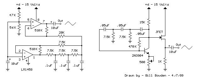
The two circuits below illustrate the generation of low-frequency sine waves by shifting the phase of the signal through an RC network, ensuring that oscillation occurs when the total phase shift reaches 360 degrees. The transistor circuit on the...
Many TOPSwitch TOP223 flyback power supply applications require two or more outputs to supply a variety of secondary circuits. Typical consumer applications of these multiple output converters include televisions and related products such as set-top decoders and video cassette...
Chapter 4, part five of a five-part series titled "Some Thoughts on DC/DC Converters," authored by the late Jim Williams and Brian Huffman, is included in Volume II of the book "Analog Circuit Design-- Immersion in the Black Art...
Connect all connectors onto the flat cable using a small vice. This creates an instant male-male, male-female, and female-female serial adapter, along with a short extender cord. This tool is essential for those experimenting with serial ports. An additional...
The connections made in this order on the connector ensure that it does not matter if the connector is inserted incorrectly, as GND and VCC are applied to the clock and data. If VCC and GND were located at...