
low frequency sinewave
The described circuits utilize two distinct methods for generating low-frequency sine waves. The first method employs a transistor-based oscillator, which relies on a 3904 transistor configured to produce a sine wave output. This circuit requires careful tuning of the gain, facilitated by a 500-ohm resistor, to achieve a stable output with minimal distortion. However, the sensitivity of this design to component variations and adjustments limits its practical application.
In contrast, the op-amp-based phase shift oscillator offers a more robust solution. This design consists of a series of RC networks that achieve the necessary phase shifts for oscillation. The op-amp's gain can be easily adjusted to exceed the minimum threshold needed for oscillation, enhancing stability and reducing the likelihood of distortion. The output derived from the RC network is buffered by a second op-amp, which not only restores the amplitude but also ensures a clean sine wave output.
The frequency of oscillation is determined by the values of the resistors and capacitors in the RC network. In this configuration, a 7.5 kΩ resistor in conjunction with a 0.1 µF capacitor yields a frequency of approximately 600 Hz. By increasing the resistance values proportionally, the frequency can be lowered, providing flexibility in application. The careful selection of components, particularly the 7.5 kΩ resistor at pin 2 of the op-amp, ensures that the output waveform remains within acceptable limits, avoiding excessive clipping and distortion.
Overall, the op-amp-based phase shift oscillator is favored for applications requiring low distortion and high stability, making it suitable for various electronic signal processing tasks. The clean sine wave output, capable of achieving around 5 volts peak-to-peak with a 12-volt supply, is an advantage that enhances its usability in practical circuits.The two circuits below illustrate generating low frequency sinewaves by shifting the phase of the signal through an RC network so that oscillation occurs where the total phase shift is 360 degrees. The transistor circuit on the right produces a reasonable sinewave at the collector of the 3904 which is buffered by the JFET to yield a low impedance
output. The circuit gain is critical for low distortion and you may need to adjust the 500 ohm resistor to achieve a stable waveform with minimum distortion. The transistor circuit is not recommended for practical applications due to the critical adjustments needed.
The op-amp based phase shift oscillator is much more stable than the single transistor version since the gain can be set higher than needed to sustain oscillation and the output is taken from the RC network which filters out most of the harmonic distortion. The sinewave output from the RC network is buffered and the amplitude restored by the second (top) op-amp which has gain of around 28dB.
Frequency is around 600 Hz for RC values shown (7. 5K and 0. 1uF) and can be reduced by proportionally increasing the network resistors (7. 5K). The 7. 5K value at pin 2 of the op-amp controls the oscillator circuit gain and is selected so that the output at pin 1 is slightly clipped at the positive and negative peaks. The sinewave output at pin 7 is about 5 volts p-p using a 12 volt supply and appears very clean on a scope since the RC network filters out most all distortion occurring at pin 1.
🔗 External reference
Related Circuits
555 low power timing circuit diagram. The diagram is from the technical information of Chinaicmart. For more detailed information about the circuit diagram. The 555 timer IC is widely utilized in various applications due to its versatility and ease of...

AC solenoid DC circuit operation operates similarly to a DC contactor circuit, but the AC solenoid pull circuit is illustrated in the provided figure. The capacitance C is generally between 1-10 microfarads (µF), with a minimum of 20 microfarads...
AM radio receivers demodulate amplitude-modulated (AM) signals. The primary source of these signals is the Standard AM Radio Broadcast Band, although shortwave stations also utilize AM modulation. Amplitude modulation was developed between 1900 and 1917 by amateur radio enthusiasts....
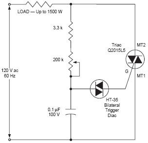
The DIAC, or diode for alternating current, is a trigger diode that conducts current only after its breakdown voltage has been momentarily exceeded. Most DIACs are utilized in applications requiring a switching function in AC circuits. The DIAC is a...
This is a low-current temperature sensor with a single-wire output. The number of pins required to interface with a microprocessor is minimized by this design. The low-current temperature sensor operates efficiently by utilizing a single-wire communication protocol, which significantly reduces...
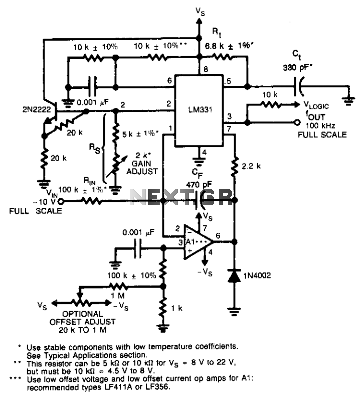
This circuit utilizes a conventional operational amplifier in conjunction with a feedback capacitor (CF) to perform integration. When the output of the integrator exceeds the nominal threshold level at pin 6 of the LM131, it triggers the timing cycle....