
simple white noise generator

The two-transistor white noise generator circuit utilizes a pair of small-signal transistors, Q1 and Q2, to produce a high level of white noise. The design leverages the inherent noise generated by the reverse-biased emitter-base junction of Q1, which acts as the primary noise source. This noise is then coupled to the base of Q2, where it is amplified.
Transistor Q1, operating in the reverse bias condition, generates noise due to the random motion of charge carriers within the semiconductor material. This noise is characterized by its broad frequency spectrum, making it suitable for applications requiring white noise.
Transistor Q2 is configured as a common-emitter amplifier, providing a significant voltage gain of approximately 45 dB. The gain is achieved through the transistor's configuration and the selection of appropriate biasing resistors, ensuring that Q2 operates within its active region. The gain can be further influenced by the choice of components in the circuit, including resistors and capacitors.
Capacitor C1 plays a crucial role in this circuit by acting as a coupling capacitor. It allows the AC component of the noise signal to pass through while blocking any DC component, thus preserving the DC biasing conditions of Q1. This ensures that Q1 remains in the correct operating region, allowing for consistent noise generation without distortion due to DC shifts.
The overall design is compact and efficient, making it suitable for various applications, including audio testing, random number generation, and other electronic applications that require a reliable source of white noise. The ability to use small-signal transistors with a high beta rating enhances the performance of the circuit, ensuring a robust noise output while maintaining low power consumption.This two-transistor white noise generator has a surprising feature about 30dB more noise than the more traditional designs. Q1 and Q2 can be any small-signal transistors with a beta of up to 400. The reverse-biased emitter-base junction of Q1 provides the noise source, which is fed into the base of Q2.
Q2 forms a simple amplifier with a gain of 45dB. The improved output level is due mainly to the inclusion of C1, which provides a low-impedance AC source to the noise source while not disturbing the DC bias of Q1.. 🔗 External reference
Related Circuits
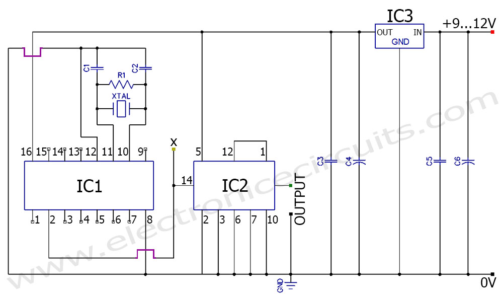
A frequency generator circuit capable of producing 50 Hz and 60 Hz outputs using a crystal oscillator. This oscillator can be utilized to generate precise frequency signals. This frequency generator circuit employs a crystal oscillator as its core component, which...
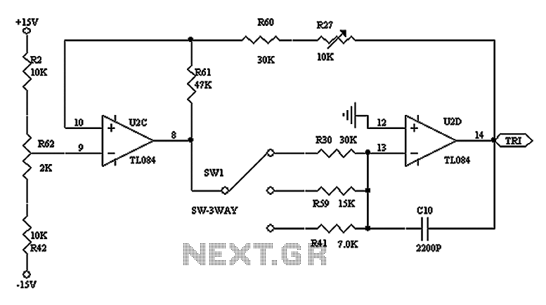
The triangular wave circuit consists of two operational amplifiers (OPs). R62 serves as the offset adjustment, while R27 is utilized for peak adjustment. A switch is included to select different resistances, allowing for the generation of triangular waves at...
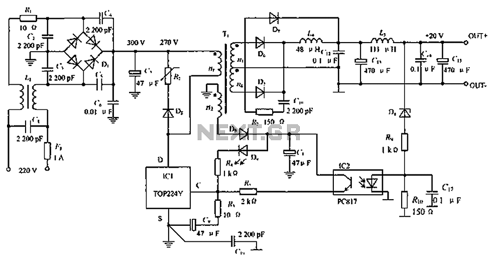
The circuit depicted in the figure is designed to achieve a higher power output by modifying specific components. On the left side of the figure, components R1, L1, D1, and capacitors C1 to C7 form a conventional filtering and...
TA1317ANG is a deflection processor integrated circuit (IC) designed for large and wide picture tubes. It includes an electronic width (EW) correction circuit, a vertical distortion correction circuit, and a dynamic focus correction circuit. The device can control various...
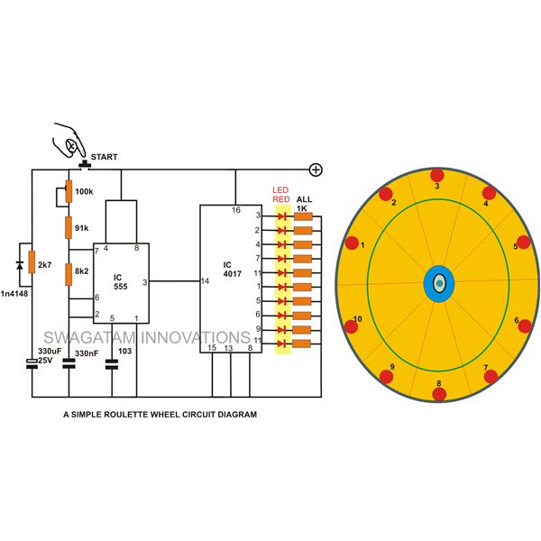
A simple circuit for a 10 LED roulette wheel is presented. Pressing the button initiates the LEDs in a rotational sequence that starts at full speed and gradually decelerates until it halts at a randomly selected LED. The randomness...
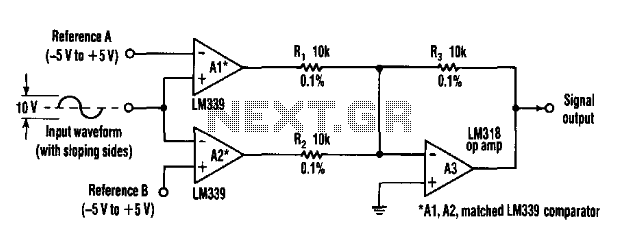
This circuit can extract harmonics from various waveforms. With a sloped input waveform, the comparator produces a pulse width that is proportional to a reference plus input amplitude. As the pulse width changes, the harmonics spectrum changes. Combining the...