
Triton Cooling Systems
The Lambda II circuit design utilizes the Atmel 8535 microcontroller as its core processing unit, operating at a frequency of 4 MHz with 8K of RAM, which provides sufficient resources for basic control applications. The choice of the Atmel 8535 over competing microcontrollers from manufacturers like Motorola or PIC is primarily attributed to the ease of programming and the cost-effectiveness of the development setup. The integration of the STK-500 development board enhances the design by allowing for straightforward programming and debugging through AVR Studio, which is pivotal for developing and refining the firmware.
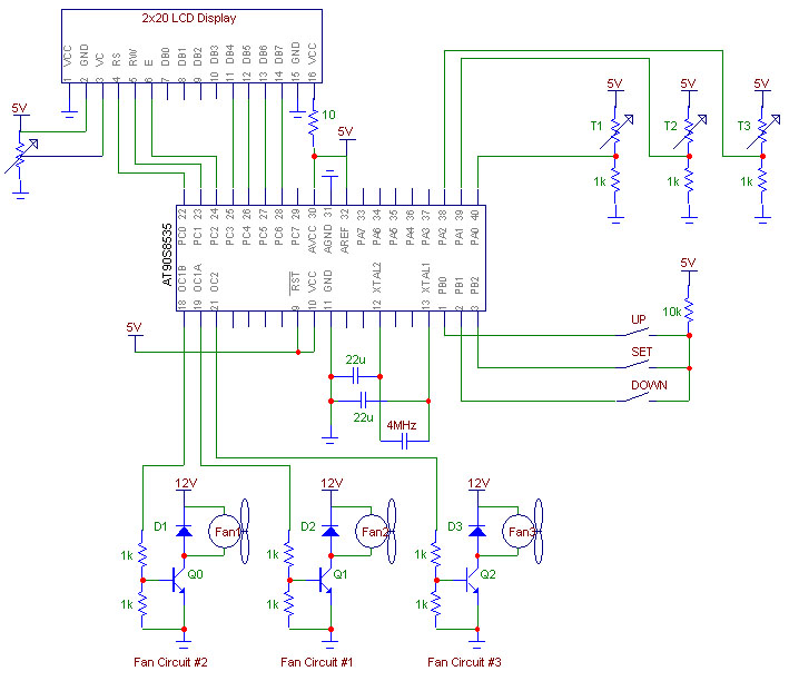
The external components connected to the microcontroller include an LCD readout, which serves as a user interface for displaying and modifying settings. The LCD is interfaced using a 4-bit data bus connected to Port C of the Atmel 8535, along with control lines that manage the display operations. This setup leverages the Hitachi HD44780 controller, widely adopted in small LCD screens, ensuring compatibility and ease of integration.
In addition to the LCD, a temperature monitoring system is implemented to gather environmental data, which can be critical for applications requiring temperature regulation. The fan control circuit employs PWM to manage the fan speed efficiently. By rapidly switching the fan's power supply on and off, PWM allows for precise control over the average voltage supplied to the fan, optimizing performance while minimizing heat generation in the control circuitry. This method is particularly advantageous in applications where thermal management is essential, as it provides a balance between effective cooling and energy efficiency.
Overall, the Lambda II project exemplifies a well-structured approach to microcontroller-based design, combining user-friendly interfaces, effective monitoring systems, and efficient control mechanisms to create a versatile and functional electronic system.The Lambda II is based upon the Atmel 8535 chip, which operates at 4 MHz and contains 8K of RAM. This chip was chosen over other brands such as Motorola or Pic, because the circuit used to program it using a computer is very simple to build. This results in an inexpensive way to get started with Atmel products. Although this programming method work s perfectly, a development board called the STK-500 was bought later on in the project. This board allows programming of any Atmel processor, and includes onboard LEDs and switches that can easily be connected to any of the ports. This simplified development and testing procedures greatly. The Atmel AVR STK500 starter kit is specially designed as a development system for Atmel ’s AVR flash microcontrollers.
The STK500 provides a quick start to develop code on the AVR combined with other features to develop prototypes and test new designs. The STK500 interfaces with AVR Studio, Atmel ’s Integrated development Environment (IDE) for code writing and debugging.
Three basic external circuits were required in addition to the Atmel 8535 microcontroller that allow the processor to be interfaced with the real world. The first is the LCD readout for monitoring and changing settings, the second is the temperature monitoring system, and the third is the fan control circuit.
Because almost all small LCD screens are based on the same controller chip, called the Hitachi HD44780, it is fairly simple to interface one to the microcontroller. The following link shows the wiring schematic from the Atmel microcontroller to the LCD readout. As shown in the figure, Port C of the Atmel 8535 is wired to the 4-bit databus and the three control lines of the LCD.
The method used to control fan speeds in this project is called Pulse Width Modulation, or PWM. This involves turning the fan ’s power supply on and off at a fixed frequency to vary the average DC voltage supplied to the fan. This method was chosen over linear regulation (simply varying the input voltage directly), because PWM offers a fairly simple drive circuit, good startup characteristics, and minimal heat dissipation in the pass transistor.
The following link shows how this circuit was set up. 🔗 External reference
Related Circuits
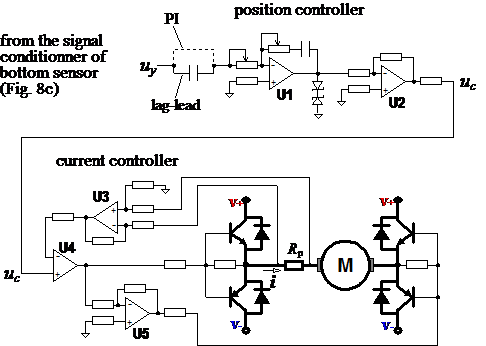
Typical solutions for the vertical movement of probes in bed profiling devices include guide wheels, dumpers, brakes, and vibration suppressors (not shown). A complete mechanism for vertical motion of a bed profiler is illustrated, featuring an electric motor, a...
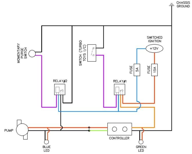
Coolingmist Stage 3 HOM Trunkmount kit installation is underway to enable continuous enjoyment of the HOM system. The setup includes a switch for arming the system and a separate push-button for purging. The intercooler sprayer assembly will be removed...
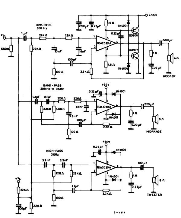
A simple multiway active speaker audio system can be designed using the TDA2030 audio IC. This TDA2030 active speaker audio system circuit is created to deliver optimal acoustic performance, as each loudspeaker is specifically designed and optimized for a...
The simulation of behavioral DSP designs alongside analog/RF circuit designs is essential for the successful integration of components, devices, and subsystems in modern wireless applications. Verifying the effects of real-world analog/RF issues on DSP algorithms, and vice versa, within...
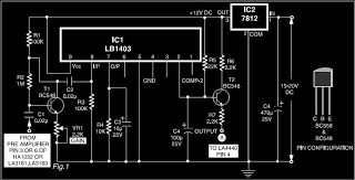
This is a circuit diagram for automatic muting in audio systems utilizing the IC LB1403. The output from a pre-amplifier, such as the LA3160, LA3161, or HA1032, is connected to the base of the amplifier transistor BC548 (T1). A...
A continuously running cooling fan can be a significant nuisance and is not essential for most instruments. The 12V smart fan control presented here allows the fan to operate only when necessary. The 12V smart fan control circuit is designed...