
TTL Load circuit

The described circuit functions as a load for an integrated circuit (IC) in various testing scenarios. The load circuit typically consists of a resistor and capacitor, which simulate the electrical characteristics of the actual load that the IC will drive. The resistor serves to limit current and establish a basic resistive load, while the capacitor accounts for the reactive component, which can affect the timing and performance of the IC.
In practical applications, the capacitor in the load circuit may represent the inherent capacitance of the load being driven or the capacitance of the measuring equipment, such as an oscilloscope probe. This dual role of the capacitor is crucial for accurate testing and measurement, as it allows for a more realistic representation of the conditions the IC will face in operation.
The circuit can be designed to include both passive and active load configurations. The passive load typically features a pull-up resistor to ensure that specific ICs, particularly those with open-collector outputs, can operate correctly. In contrast, the active load configuration employs diodes that provide a more dynamic and realistic load condition, modeling the behavior of another IC that the DUT may interface with.
The inclusion of input capacitance is essential for accurate performance analysis. Each IC input inherently has some capacitance, which can affect switching times and signal integrity. Therefore, it is recommended to include this capacitance in the load circuit to replicate real-world conditions. When testing, it is also beneficial to account for additional capacitance from test jigs, which can further refine the accuracy of the measurements.
Datasheets for ICs often provide load capacitance values that can be used to gauge the expected performance and switching characteristics. However, it is not uncommon for the datasheet to specify an input capacitance (Ci) that is lower than the load capacitance (CL) used in timing measurements. This discrepancy highlights the need for careful consideration of both parameters when evaluating IC performance.
In summary, the load circuit described plays a critical role in testing integrated circuits by simulating the electrical characteristics of the loads they will encounter in real-world applications. The careful selection and configuration of resistive and capacitive components, along with an understanding of the nuances in datasheet specifications, are vital for accurate performance analysis and circuit design.A device through which an electric current flows and which changes electrical energy into another form. Power consumed by a device or circuit in performing its function. A load my be represented by a resistor and capacitor. The capacitor used in the load circuit is there to represent the capacitance of the load the IC is driving.
However the capacitor may also represent the capacitance of the measuring device used to verify how the IC works with the load [as in the capacitance of the scope probe]. There are two other types of TTL loads; a standard resistive load, or an active load. The active load using diodes insures the Device under Test [ DUT ] switches a more realistic load which mimics another IC load.
The passive load shown includes a pull-up resistor only because some ICs need to be pulled high to operate [as in an open-collector]. Every input to an IC has some capacitance, so the load should include some value of capacitance. Including an additional value to account for the test jig makes the circuit more realistic. Many data sheet do not provide an estimate of input capacitance, which would be the capacitive load seen by the IC driving the chip.
However in many cases the data sheet does provide a load capacitance to determine switching time in the electrical characteristics portion of the data sheet. That value or range of values of load capacitance could be used to determine input capacitance [Ci] when using ICs of the same logic family.
Then again, in a few cases an input capacitance is provided, which happens to be much lower than the Load Capacitor [CL] used in the timing measurements. For example a Ci of 2. 6pF is provided by the 54ACT11 data sheet, while at the same time a value of 50pF CL is used in the timing characteristics.
The difference in capacitor value is the difference between what is expected through design [Ci], and what is expected in a worst case circuit example [CL]. The input capacitance is designed into the IC at the time of fabrication, with some variation. However the load capacitance seen by the driver can not be determined and will vary depending on the integrated circuit used receiving the signal.
🔗 External reference
Related Circuits
Commercial FM demodulation occurs at an intermediate frequency (IF) of 10.7 MHz. With a frequency deviation of ±75 kHz, the deviation of the IF carrier is approximately ±0.7%. This deviation allows for the conversion of FM to AM or...
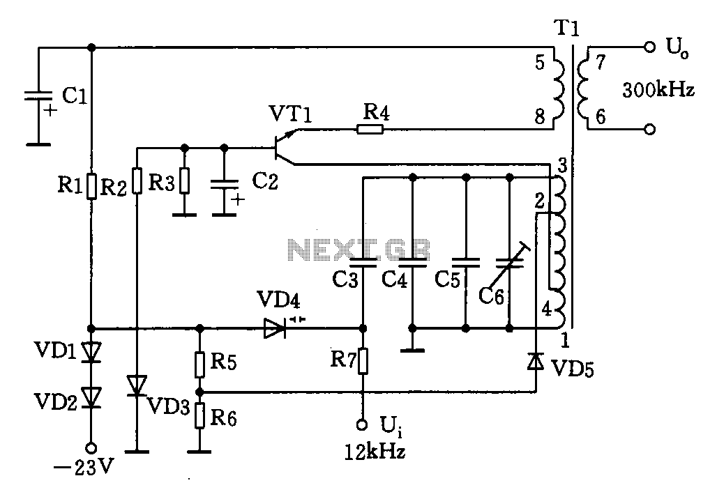
This circuit is designed for a 300 kHz signal generator. It includes components such as VT1, T1, VD4, and other associated elements. The voltage-controlled oscillator (VCO) employs an LC-tuned collector, with VT1 functioning as the oscillating transistor, varactor diode...
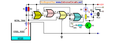
This circuit utilizes a relay to control a water pump for automatic level regulation of a water reservoir or well. The shorter steel rod acts as a high water sensor, while the longer rod serves as a low water...
A thermistor positioned as indicated creates a heat-activated sensor. Variations in temperature will modify the output of the operational amplifier, triggering the relay and illuminating the LED. Reversing the placement of the thermistor and the 47k resistor converts the...
This decibel meter circuit responds to sound pressure levels ranging from approximately 60 to 70 dB (decibels). The sound is captured by an 8-ohm speaker and amplified using a transistor stage along with an LM324 operational amplifier section. A...

The schematic for this project is designed to be very simple, utilizing a minimal number of components to keep costs and assembly time low. The primary components in the schematic include the PIC 18F452 microcontroller, a tilt sensor, and...