
Integrated Circuits
The 555 timer IC is widely recognized for its versatility and ease of use in various electronic applications. It can operate in three primary modes: astable, monostable, and bistable, each serving different timing and control functions. In astable mode, the 555 functions as an oscillator, generating a continuous square wave output, which is ideal for applications like LED blinking or tone generation. In monostable mode, the IC produces a single output pulse in response to a trigger input, making it suitable for applications requiring a timed delay or pulse generation. Bistable mode allows the 555 to act as a flip-flop, maintaining its output state until triggered by an external signal, which is useful in memory storage applications.
The configuration of external components, such as resistors and capacitors, plays a crucial role in determining the timing characteristics of the 555 timer. The time period for astable operation can be calculated using the formula T = 0.693 × (R1 + 2R2) × C, where T is the period, R1 and R2 are the resistances, and C is the capacitance. For monostable operation, the pulse width can be determined by the formula T = 1.1 × R × C.
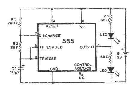
The pin configuration of the 555 timer is standardized, allowing for consistent integration into various circuit designs. Pin 1 is the ground connection, while pin 8 is the supply voltage. Pins 2 and 6 are connected to the trigger and threshold inputs, respectively, enabling the timing functions. Pin 3 serves as the output, providing the timed signal, while pins 4 and 8 control the reset and supply voltage, ensuring proper operation.
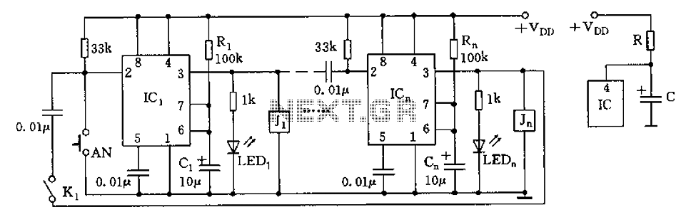
In summary, the 555 timer IC is an essential component in the electronics field, offering a broad range of functionality through its various operating modes. Understanding its operation and configuration allows engineers and hobbyists alike to create diverse applications, from simple timers to complex waveform generators. Accessing the manufacturer's datasheet is critical for detailed specifications and application examples, facilitating effective implementation in electronic projects.An Intergrated ircuit is just that. an intergrated circuit. These small packages combine many individual components to perform a specific function. They vary in shape and size depending on their complexity. They are categorised into functions like Audio, Digital, Timers and many special functions. The limit is almost endless. The 555 ICis a univer sal timer used for many purposes and in the case above to flash LEDs on and off. With the help of a few external components, the 555 can precisely calculate time. How this is done is usually of no concern to electronics enthusiasts - as long as it works! However a basic overview may be interesting: The figure below shows a functional block diagram of the 555. The dotted line is the chip with leg numbers shown. External components around the chip give flexability to the timer - a 5 minute timer would have different external components to a 30 minute timer.
Leg numbers follow a convention. The top of the chip is indicated by a circle or notch at the top. With the chip in this orientation, the top left pin in pin 1 - counting down to the bottom left pin then up the right side. Searching the manufacturers website will yeild data sheets for IC`s you are using. These data sheets have all the information needed to use the chips - a sample data sheet : LM 555 Data Sheet
🔗 External reference
Related Circuits
The AM transmitter circuit consists of an audio amplifier and an RF oscillator. The oscillator is constructed around transistor Q1 and its associated components. The tank circuit, which includes inductor L1 and variable capacitor VC1, is tunable from approximately...
Electron trajectories in a conductor are depicted in the diagrams below. When no electric field is present inside a conducting material, electrons move randomly. However, when an electric field is applied, the electric force F = qE induces a...
An advantage of a photogate over a sound trigger is that the former activates based on the exact position of the object that interrupts the beam. For instance, the shape of a snapped elastic cord can be captured as...
The circuit depicted in the figure is designed for multi-temperature testing, allowing for the switching of the thermocouple corresponding to the active channel. At the core of this design is a 555 timer configured in a monostable delay mode....
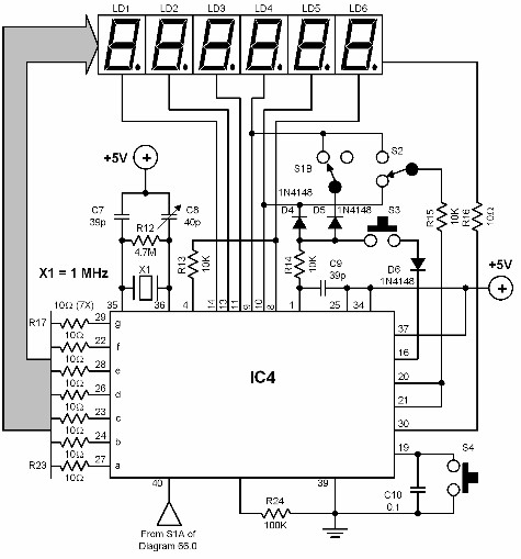
A digital audio frequency (AF) counter can be constructed using a minimal number of components by employing a single 7226B integrated circuit (IC) from Intensil, as depicted in the accompanying diagram. This circuit has an upper frequency limit of...
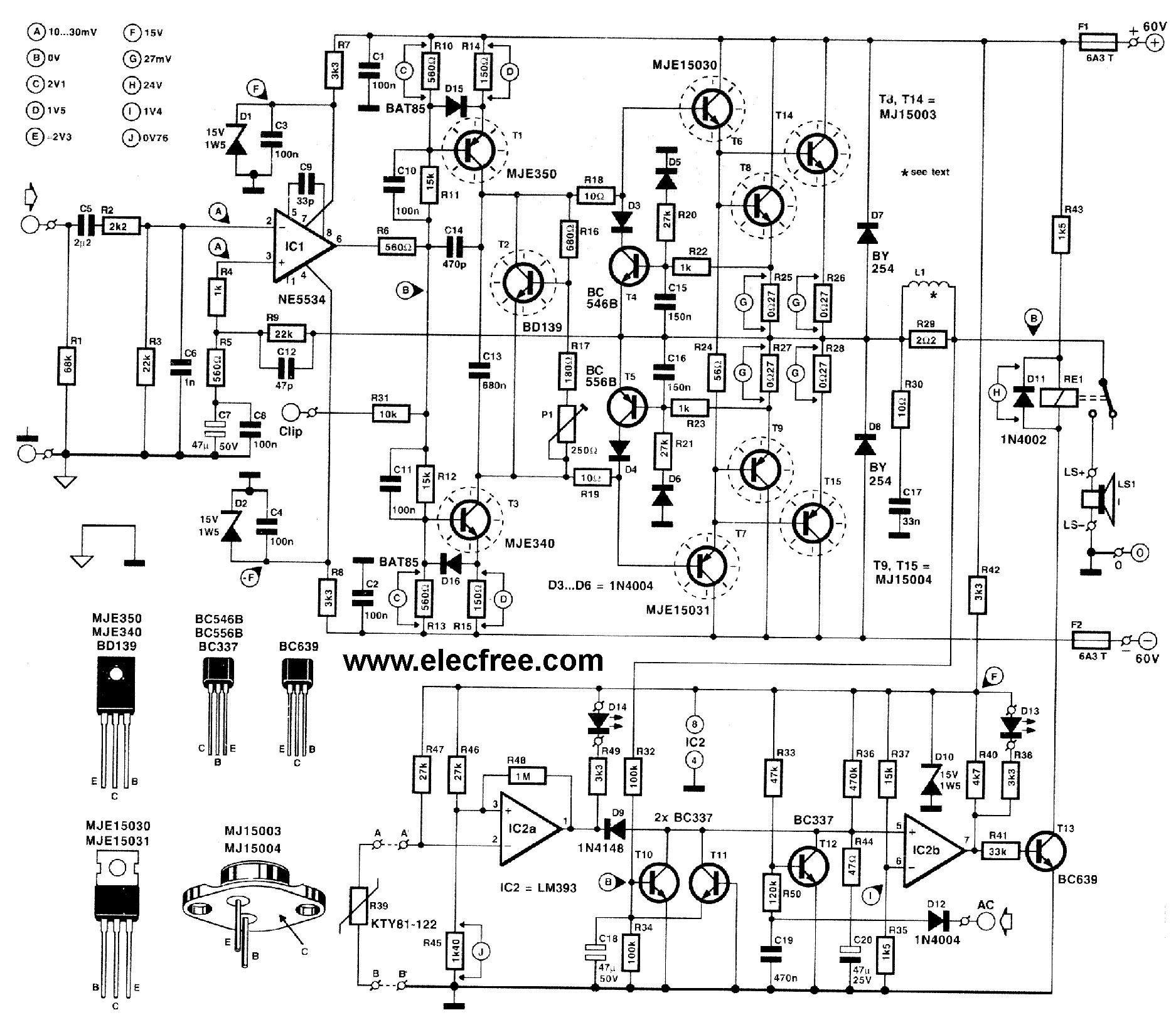
This circuit is designed for friends who are interested in high-power amplifier circuits. It can deliver approximately 300 Watts RMS and operates as an OCL (Output Capacitor-Less) Class AB amplifier, providing high sound power while systematically protecting the loudspeaker...