
Four reverse brake circuits to operate energy

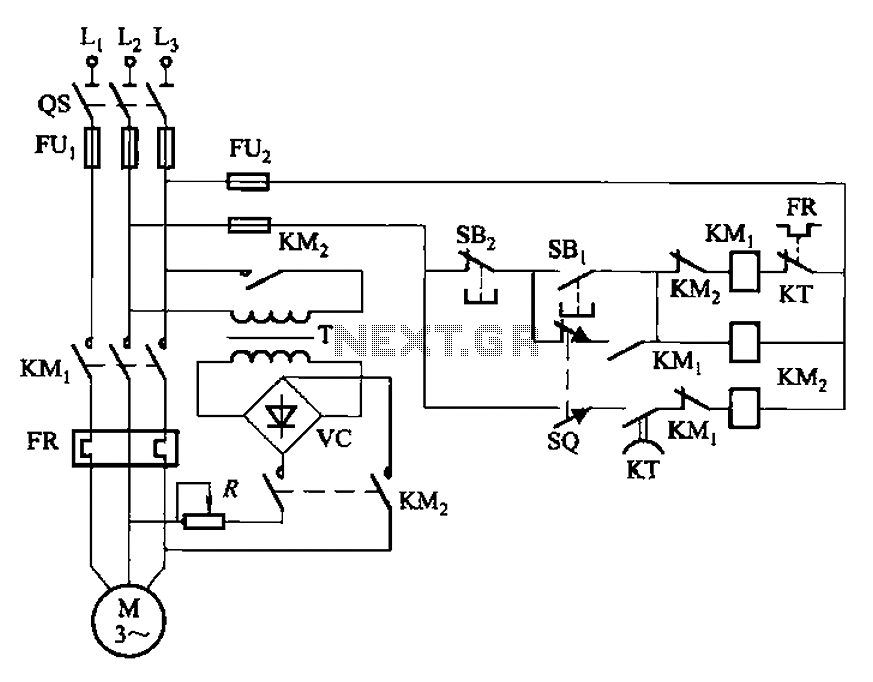
The circuit employs a time relay (KT) that plays a critical role in managing the braking process. By adjusting the relay's timing from 1 to 2 seconds, it can accommodate various operational conditions, ensuring that the braking action is neither too abrupt nor too prolonged. This adjustment is vital for applications where precision in stopping is necessary to prevent mechanical stress or damage to the system.
The forward and reverse operation terminal switches, SQ1 and SQ2, are integral to controlling the direction of motion in the system. These limit switches are activated when the mechanism reaches its respective end positions, ensuring that the motor does not exceed its designated operational range. This feature is crucial in automated systems where precise control of movement is required for safety and efficiency.
Incorporating these components into the circuit design enhances the overall reliability and performance of the braking system. The combination of the time relay and limit switches allows for a well-coordinated operation that minimizes the risk of mechanical failure and enhances user safety. The circuit's layout should be carefully designed to ensure that all connections are secure and that the relay and switches are positioned for optimal functionality within the broader system. Circuit shown in Figure 3-147. To allow sufficient braking time, using the time relay KT (1 ~ 2s, adjustable), the real on the occasion of a brake stop time may be short. Figur e, SQi, SQ2 respectively forward and reverse operation terminal (limit) switches.
Related Circuits
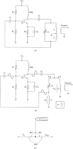
A widely recognized circuit is the Hartley oscillator, which is characterized by a tapped coil within the LC tank circuit. The tap point of the coil is grounded. The oscillator's amplifier section functions as a common-emitter amplifier, resulting in...
Introduction The MIC2290 is an internally compensated standard step-up switching regulator that features an integrated power switch and Schottky diode. The inclusion of these components makes the MIC2290 an optimal solution for 48V Avalanche Photo Diode (APD) applications. In...
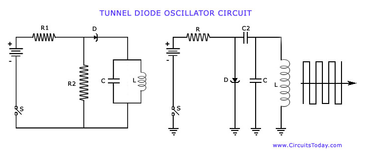
The operation of Negative Resistance Oscillators, including types such as Dynatron and Tunnel Diode Oscillator, along with their characteristics and circuit diagrams, is explained. Negative resistance oscillators are electronic circuits that exploit the phenomenon of negative resistance to generate oscillations....
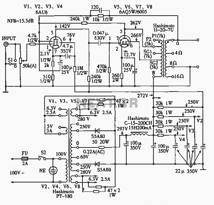
The 6AQ5W / 6005UL four-channel single-ended amplifier circuit is illustrated in the accompanying figure. Only two channels are shown, but it is part of a four-channel system that employs a power transformer for the voltage amplification section. This section...

This circuit was designed on request to drive a Light-cluster formed by several LEDs that can be mounted in the vehicle as a tail and brake light. When SW1 is on, the cluster will illuminate at medium brightness. When...
The circuit illustrated in Figure 3-136 incorporates a limit switch (SQ) that, when the motor operates a mechanical device to reach a predetermined position, cuts off the power and initiates dynamic braking for fast and accurate positioning. This configuration...