
Tube Power Amplifier with EL34 - 35W circuit
The described amplifier features a push-pull topology, which is well-known for its efficiency in audio amplification. The use of two EL34 vacuum tubes allows for a robust output of 35 watts, making it suitable for driving speakers in various audio applications. The push-pull configuration provides advantages such as reduced distortion and improved linearity, which are crucial for high-fidelity sound reproduction.
The circuit likely includes a power supply section designed to provide the necessary high voltage for the EL34 tubes, as well as filament voltage for their operation. The output stage would typically incorporate an output transformer, which matches the high-impedance output of the tubes to the low-impedance load of the speakers. Additionally, feedback mechanisms may be implemented to further enhance performance by stabilizing gain and reducing distortion.
Given the long operational lifespan of the amplifier, it is essential to consider the durability and reliability of components used in the design. High-quality capacitors and resistors would be necessary to maintain performance over time, especially under continuous use for 15 hours daily. The original design from 1953 reflects the engineering standards of the era while providing a foundation for audio amplification that remains appreciated by enthusiasts today.It`s a classic designing of final amplifier 35 W, with two EL34 in push-pull, from the Siemens and Halske, with year of designing 24/3/1953 and code SV410/1. The amplifier it worked from 1954 until 1989, whenever it came also out except operation, with mean of operation 15 hours per day..
🔗 External reference
Related Circuits
The 8-pin 555 timer is one of the most versatile integrated circuits (ICs) available, utilized in numerous projects. With minimal external components, it can be employed to construct various circuits, many of which do not pertain to timing applications....

The TEA5551T monolithic integrated radio circuit can be utilized to design an AM radio receiver, intended for use as a portable radio receiver with headphones. The TEA5551T radio receiver circuit encompasses all necessary components for a complete AM receiver,...
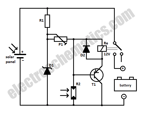
When charging a battery during the day using a solar panel, there is a risk of the battery partially discharging through the panel after sunset. This solar panel power switch circuit eliminates the need for a diode by utilizing...
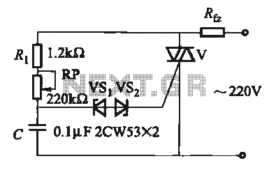
The introduction for a unidirectional thyristor trigger circuit is also applicable to the TRIAC. Several bidirectional circuits are illustrated in Figure 16-28. Figures 16-28 (a) and (b) depict a direct trigger circuit; Figure 16-28 (c) illustrates a dual diode...
The circuit (before flameout) worked like this: device Q1 is a triac, which is a power-switching device. When triggered, it switches to a fully conducting state and stays that way until the current passing through it goes to zero....
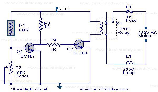
The circuit diagram of an Automatic Street Light Controller Circuit is explained in this post. The Automatic Street Light Controller Circuit is designed to automatically turn on street lights at dusk and turn them off at dawn. This functionality is...