
Tunable active filter

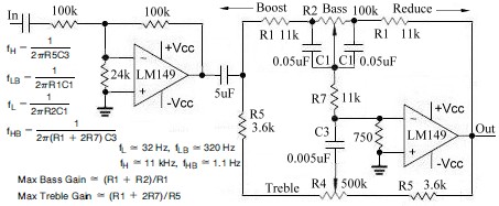
The described circuit features a fixed-frequency active filter designed to manipulate audio signals by selectively allowing or attenuating certain frequency ranges. The high-pass and low-pass outputs are configured to operate within the frequency range of 300 Hz to 3000 Hz, which is typical for audio processing applications, ensuring that both low and high frequencies can be effectively managed.
The use of potentiometers with a reverse log taper is critical in this design. This type of taper allows for more precise control over the attenuation and gain of the audio signals at lower levels, making it particularly suitable for audio applications where fine adjustments are necessary.
The circuit includes a fourth operational amplifier (op-amp), which serves the purpose of summing the outputs of the high-pass and low-pass filters. This op-amp configuration is essential for creating a notch filter that is centered at a frequency of 1 kHz. The Q factor, which is set at 50, indicates a narrow bandwidth around the center frequency, allowing for selective attenuation of signals at 1 kHz while preserving signals outside this frequency. This characteristic is beneficial in applications such as feedback suppression in audio systems or in environments with specific noise frequencies that need to be minimized.
Overall, this circuit design is an effective solution for audio signal processing, providing both flexibility and precision in frequency management.The high-pass and low-pass outputs cov- output. The potentiometers must have a re-ering the range of 300 Hz to 3000 Hz have been verse log taper Fixed-frequency active filter summed in the fourth op amp to provide a notch center frequency is 1 kHz, with a Q of 50. 🔗 External reference
Related Circuits
The use of optical filters to reduce or eliminate light from other sources is discussed. A narrowband optical filter on the receiver can reject "off-wavelength" light; however, these filters tend to be expensive and challenging to implement in simple...
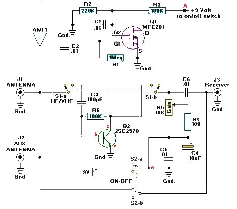
A simple and efficient active antenna electronic project can be designed using this electronic schematic circuit based on transistors. This active antenna project is effective for a wide range of RF frequencies, covering three RF bands: HF, VHF, and...
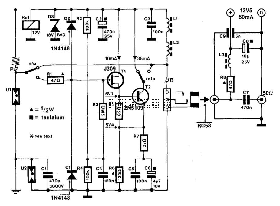
A J309 Siliconix FET is utilized to drive a 2N5109 in a wideband RF amplifier setup. A relay is incorporated to bypass the amplifier in transmit mode, if required. An active antenna element is a 2-meter 5/8-wave whip. The...
This topic continues from the more general Passive Tone Control circuit, which begins using only passive filters. This circuit follows the previous design, although the component values are different and in an alternate configuration. An audio tone control combines...
What is the purpose of this circuit? Basically it has two roles: to pass the desired low frequency signals and stop the unwanted high frequency signals. Open the netlist file lpfilter1.cir with your SPICE simulator. Most simulators display the...
The elements and internal function diagram are depicted in Figure 9-50. Capacitors C1, C2, and C3 represent feedback capacitance, which changes with low-frequency variations within a specific cutoff frequency range. Capacitor C5 serves as the output coupling capacitor, typically...