
Tic Tac Tunes Circuit Diagram

In this circuit design, the primary power source is a compact 6V battery, which is advantageous in applications where space constraints are significant. To achieve the desired operating voltage of 4.8V for the PicAxe microcontroller, two silicon diodes, labeled D1 and D2, are used in series. Each diode typically has a forward voltage drop of approximately 0.6V to 0.7V, thus the combined drop across both diodes results in a total reduction of about 1.2V from the initial 6V supply.
The PicAxe chip, a popular microcontroller for educational and hobbyist projects, operates efficiently at 4.8V. This voltage level is crucial for ensuring the chip functions correctly without risking damage from overvoltage. The circuit may also include additional passive components, such as capacitors for smoothing and filtering purposes, to stabilize the voltage supply to the microcontroller and mitigate any noise.
It is important to consider the current requirements of the PicAxe chip and ensure that the diodes selected can handle the load without overheating or exceeding their current ratings. The choice of diodes should also account for their reverse voltage ratings to prevent breakdown in case of reverse polarity connections.
In summary, this circuit effectively utilizes a small 6V battery and employs two diodes to achieve a regulated 4.8V supply for the PicAxe microcontroller, making it suitable for compact electronic projects where space is limited.As space is at a premium here, I`m using a small 6V battery and dropping the voltage down by 1.2V to 4.8V with the diodes D1 and D2. The PicAxe chip.. 🔗 External reference
Related Circuits

High Power Siren Circuit. This article discusses a robust siren circuit suitable for various applications. A complementary transistor pair (BC557 & BC337) is configured as an oscillator to directly drive the speaker. Transistor Q1 (BC557) is utilized to ensure...
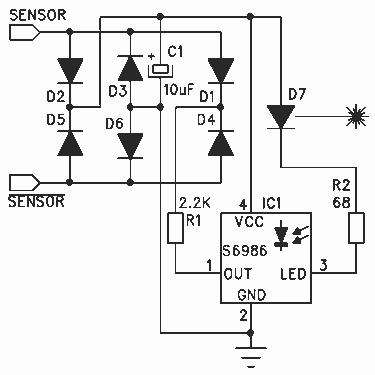
Thanks to the S6986, the circuit is very simple and requires few components. D2, D3, D5 and D6 forms a bridge rectifier allowing to plug the sensor connector brick in any direction. C1 filters power supply, it must be...
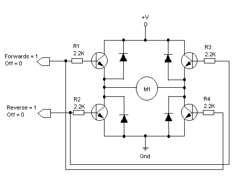
The principles of DC motors are discussed in the beginner and intermediate sections of this tutorial. This section will address the electronics required to interface them with a Basic X microcontroller or other digital chips. The simplest method of...
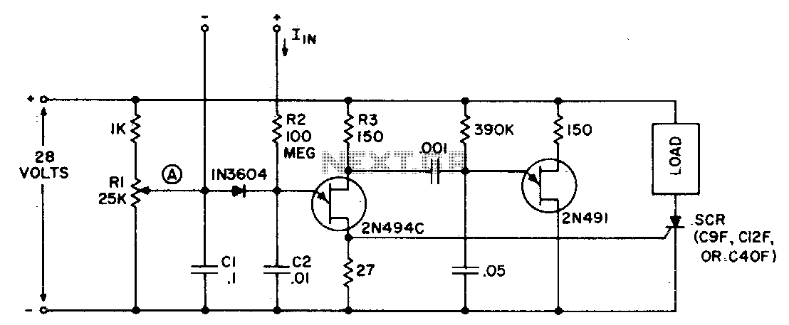
The circuit can function as a sensitive current detector or a voltage detector with high input impedance. Resistor Rl is configured so that the voltage at point (A) is V2 to a few volts below the threshold that activates...

The capacitor C is part of the speed differential negative feedback system. The adjustment potentiometer RP allows for changing the amount of negative feedback. Both components can be utilized simultaneously within the circuit. The voltage (or speed) will only...
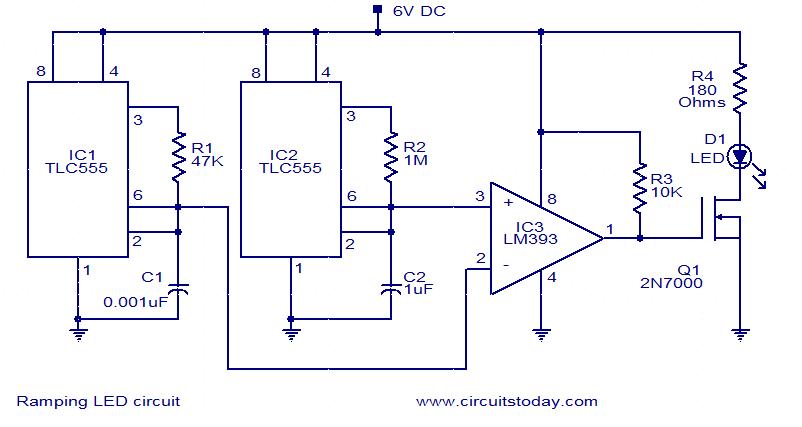
In this circuit, the intensity of the LED varies in a ramping fashion. The circuit comprises three integrated circuits: two 555 timer ICs and one LM393 operational amplifier. IC1 and IC2 are configured as oscillators to generate frequencies of...
Warning: include(partials/cookie-banner.php): Failed to open stream: Permission denied in /var/www/html/nextgr/view-circuit.php on line 713
Warning: include(): Failed opening 'partials/cookie-banner.php' for inclusion (include_path='.:/usr/share/php') in /var/www/html/nextgr/view-circuit.php on line 713