
Tuned LC Oscillator Tutorial and Oscillator Basics

No description available.
Related Circuits
The figure illustrates the FM modulation circuit of a crystal oscillator. FM modulation can be achieved through direct and indirect methods. The direct FM method involves directly altering the frequency of the oscillating circuit. While this approach is straightforward,...
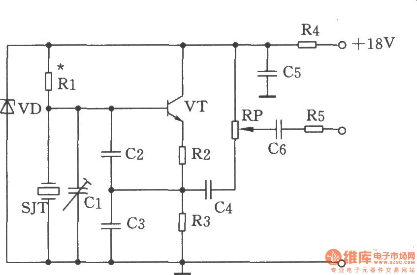
The figure illustrates the Colpitts oscillator circuit, which utilizes a base frequency crystal. The operating frequency is 1499 kHz, with the crystal SJT connected to both ends of capacitors C2 and C3. The emitter divider resistors R2 and R3...
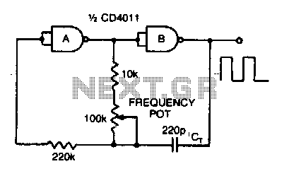
Adjusting the 100 K ohm potentiometer modifies the discharge rate of capacitor Ct, thereby affecting the output frequency. A square wave output is produced. The maximum frequency achievable with CMOS technology is constrained to 2 MHz. The circuit described involves...
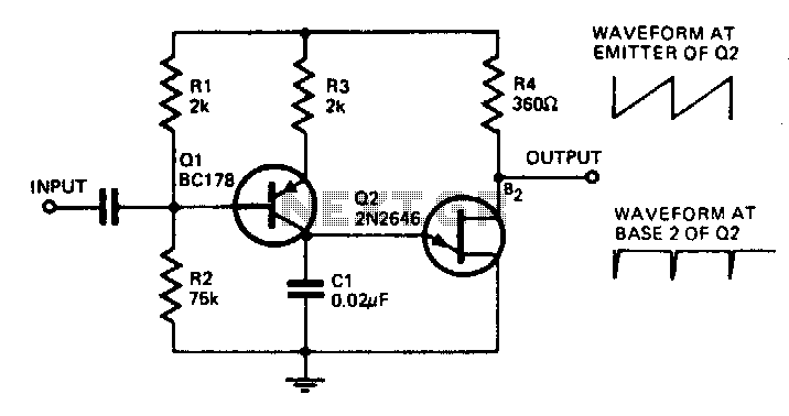
With the component values shown, the oscillator has a frequency of 8 kHz. When an input signal is applied to the base of Q1, the current flowing through Q1 is varied, thus affecting the time required to charge C1....
C1 = 100 nF multilayer or ceramic capacitor; C2 = 4.7 pF ceramic capacitor; C3 = 100 nF ceramic capacitor (1 nF or 10 nF can also be used); C4 = 40 pF trimmer capacitor; C5 = 4.7 pF...
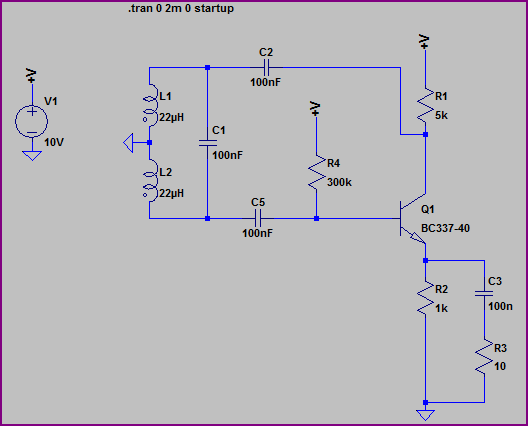
A Hartley Oscillator circuit can be constructed using a pair of series-connected coils. Two 22mH fixed inductors were utilized on a breadboard along with other necessary components. Testing the transistor amplifier independently indicated proper functionality; however, there is no...