
tuned sine wave oscillator circuit

The sine wave oscillator circuit operates by leveraging the characteristics of operational amplifiers to create stable waveforms. The LM111 and LM101A op-amps are configured in such a manner that they can generate both sine and square wave outputs. The tuning of the circuit is primarily achieved through the adjustment of R3, which allows for fine-tuning of the oscillation frequency without altering the overall gain or bandwidth of the circuit.
The feedback loop is critical for sustaining oscillations. The sine wave output generated by the tuned circuit is fed into the comparator, which converts the sine wave into a square wave. This square wave is then reinjected into the input of the tuned circuit, thus reinforcing the oscillation process. The Zener diode, D1, plays a vital role in maintaining a consistent amplitude for the feedback square wave, ensuring that the oscillator operates reliably across its frequency range.
The components R6 and C5 are essential for establishing the initial conditions necessary for the comparator to function effectively. By providing DC negative feedback, they ensure that the comparator remains in the active region, which is crucial for the initiation of oscillation. This configuration allows for a robust and versatile sine wave oscillator that can be employed in various applications requiring precise waveform generation. The design is particularly useful in audio applications, signal processing, and testing environments where a stable frequency output is essential.This is a design circuit for sine wave oscillators that will provide both a sine and square wave output for frequencies from below 20 Hz to above 20 KHz. The frequency of oscillation is easily tuned by varying a single resistor. This circuit is controlled by two op amp, LM111 and LM101A. This is the figure of the circuit. In this circuit, an opera tional amplifier has function as a tuned circuit, driven by square wave from a voltage comparator. The frequency is controlled by R1, R2, C1, C2, and R3, with R3 used for tuning. Tuning the filter does not affect its gain or bandwidth so the output amplitude does not change with frequency. A comparator is fed with the sine wave output to obtain a square wave. The square wave is then fed back to the input of the tuned circuit to cause oscillation. Zener diode, D1, stabilizes the amplitude of the square wave fed back to the filter input. Starting is insured by R6 and C5 which provide dc negative feedback around the comparator. This keeps the comparator in the active region. [Schematic diagram source: National Semiconductor. Inc] 🔗 External reference
Related Circuits
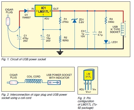
The safe 12V car adapter described here can be used to limit the current from a +12 volt car battery, available from the in-dash cigar lighter power port, to below 2.6A. The 12V car adapter is designed to ensure that...

The generated alternating current (AC) at both ends of the voltage is adjusted after being rectified to supply the motor armature windings, allowing for speed adjustments of a 15W lamp. It is noteworthy that despite the freewheeling role of...
This is a differentiator circuit. This circuit can be used to perform differential operations. There are two types of differentiators: the true differentiator and another type. A differentiator circuit is designed to output a voltage that is proportional to the...
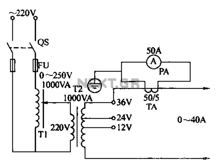
Electricians sometimes use overcurrent relays, thermal relays, and other devices to perform periodic overcurrent checks with a current generator. A secure running lights transformer, voltage regulator, and meter can be constructed using a small electric current generator. The homemade...
The PIC16F84A digital thermometer circuit is constructed primarily using a temperature sensor along with various discrete components. The PIC16F84A microcontroller serves as the core processing unit of the digital thermometer circuit. It is equipped with an 8-bit architecture and supports...
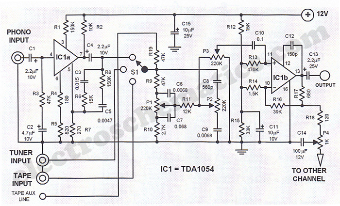
This Hi-Fi stereo preamplifier circuit is designed using the TDA1054 integrated circuit from SGS. The TDA1054 is a 16-pin DIL package that incorporates two separate preamplifier circuits. It is a low-noise preamplifier with minimal complications in the design process....
Warning: include(partials/cookie-banner.php): Failed to open stream: Permission denied in /var/www/html/nextgr/view-circuit.php on line 713
Warning: include(): Failed opening 'partials/cookie-banner.php' for inclusion (include_path='.:/usr/share/php') in /var/www/html/nextgr/view-circuit.php on line 713