
hi fi stereo preamplifier circuit
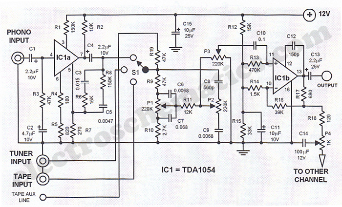
The Hi-Fi stereo preamplifier circuit utilizing the TDA1054 IC is engineered for high-performance audio applications, ensuring low distortion and noise levels. The TDA1054 integrates two independent preamplifier stages, allowing for effective amplification of audio signals from various sources. The input sensitivity of 3 mV provides compatibility with a range of audio devices, particularly turntables, which typically output low-level signals.
The frequency response is tailored through passive components C5, C3, R6, and R8, which are strategically selected to optimize the audio quality. The design emphasizes bass amplification, which enhances the low-frequency response, while treble attenuation helps to mitigate potential harshness in high-frequency signals. This selective amplification creates a balanced auditory experience, particularly beneficial for vinyl playback.
Switch S1 facilitates the selection of different audio sources, enhancing the versatility of the preamplifier. The dual potentiometer configuration with P1 and P2 allows for precise adjustments of treble and bass levels, catering to individual listener preferences. The passive tone controls ensure that the circuit maintains a clean signal path, minimizing the risk of overdrive and distortion, which is crucial in high-fidelity audio systems.
P3 plays a significant role in adjusting the signal level sent to the operational amplifier stage (IC1b), ensuring that the subsequent amplification is appropriately matched to the input levels. This stage further enhances the audio signal, providing additional gain as required.
P4's balance control is a critical feature for stereo applications, allowing for fine-tuning of the audio output between the left and right channels. The gain settings ensure that even with adjustments, the audio remains well-balanced and free from significant discrepancies between channels. This design consideration is essential for achieving a cohesive stereo soundstage, particularly in critical listening environments.
Overall, the TDA1054-based Hi-Fi stereo preamplifier circuit exemplifies a robust design approach, combining flexibility, performance, and user control to deliver high-quality audio reproduction.This Hi Fi stereo preamplifier ambit is congenital with TDA1054 IC from SGS. TDA1054 is a 16-pin DIL amalgamation and integrates 2 abstracted preamp circuits. It is a low babble preamp with little or no botheration in the architecture process. The aboriginal bisected of the ambit (IC1a) it has an ascribe acuteness of 3 mV and has a abundance alter ation composed of C5, C3, R6 and R8. The bass arresting advancing from phono ascribe is amplified while the aerial arresting is attenuated. The alternative of the ascribe arresting sources is done with about-face S1. P1 and P2 are parte of a bifold potentiometer. They ascendancy the aerial tones and bass. There is no accident of overdrive in ambit due to the acquiescent attributes of the complete control.
P3 controls the aggregate of the arresting fed to se additional allotment of the ambit (IC1b) which functions as an operational amplifier. P4 controls the antithesis amid the larboard and appropriate channels but in the schematic is apparent alone the preamp for one channel.
Both approach accept a accretion of 24 at the average ambience of P4. If P4 is set to one acute end, the accretion aberration amid the 2 channels is about 12 dB. 🔗 External reference
Related Circuits
Hobby servos convert DMX signals into mechanical motion. Typically, hobby servos require a pulse with a variable width ranging from 1 to 2 milliseconds, with 1.5 milliseconds representing the center position. The schematic below illustrates a simple voltage-to-pulse-width circuit....
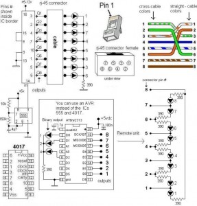
A LAN tester circuit diagram is presented in two designs. The first design utilizes a timer IC 555 and a decade counter 4017. The second design employs a microcontroller ATtiny2313. The first design of the LAN tester circuit incorporates the...
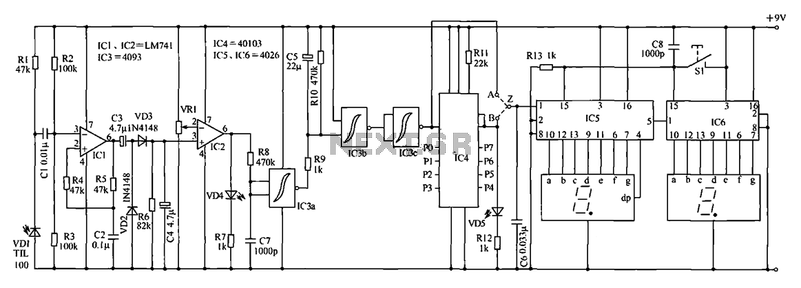
The digital counter circuit described utilizes an infrared signal to detect moving targets, making it suitable for counting small devices on a production line as they move along a conveyor belt. This circuit can also be employed for various...
This LED flasher circuit is a classic two-transistor flip-flop. It is a popular circuit often built by beginners in the electronics hobby. The schematic diagram of this well-known LED flasher circuit includes two transistors, two capacitors, four resistors, and...
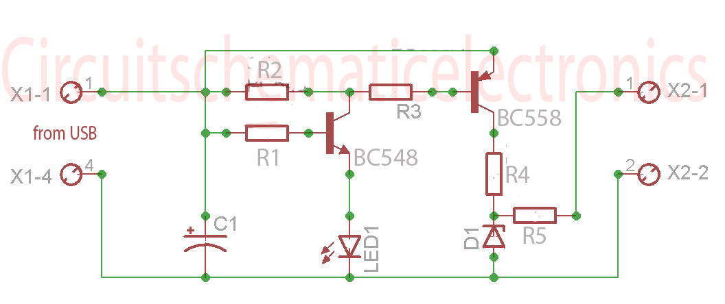
Without a USB to phone battery charger circuit, charging a phone battery using a USB port on a computer can quickly damage the battery, resulting in bulging. This occurs because the voltage output from USB is 5 volts, while...
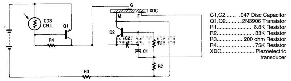
The alarm utilizes a fixed-frequency piezoelectric buzzer alongside a cadmium-sulfide (CDS) cell and a two-transistor circuit to create a distinctive effect. When light reaches the CDS photoelectric cell, the alarm remains silent. However, in the absence of light, transistor...
Warning: include(partials/cookie-banner.php): Failed to open stream: Permission denied in /var/www/html/nextgr/view-circuit.php on line 713
Warning: include(): Failed opening 'partials/cookie-banner.php' for inclusion (include_path='.:/usr/share/php') in /var/www/html/nextgr/view-circuit.php on line 713