
TV REMOTE JAMMER CIRCUIT USING 555 TIMER
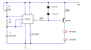
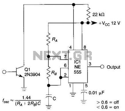
The TV remote jammer circuit primarily utilizes the NE555 timer IC configured in astable mode to generate a continuous square wave output at the desired frequency. The choice of resistors and the capacitor in the timing network is crucial as it directly influences the frequency of oscillation. In this configuration, RA and RB set the charge and discharge times of the capacitor, thereby establishing the frequency of the output waveform.
The PNP transistor SK100 is selected for its ability to handle the current required to drive the IR LED. When the NE555 output goes low, it turns on the transistor, allowing current to flow through the IR LED. This LED is designed to emit infrared light at the specified frequency of 12 kHz, which effectively disrupts the communication between the TV remote and the television set.
The overall design of the circuit is straightforward, making it accessible for hobbyists and those interested in electronics. The components required are inexpensive and readily available, allowing for easy assembly. Safety precautions should be taken into account when constructing and operating the circuit, particularly concerning the power supply and handling of electronic components. The jamming effect can be tested by attempting to use a remote control in the vicinity of the circuit to observe the disruption in functionality.A Tv remote jammer circuit, using NE555 timer IC. By using this you can watch your favorite TV channel without any interruptions. Ie; No one can be able to change the channel by means of remote, if the circuit remains ON. The circuit is simple to make at your own home, with very low cost. Let`s go deeply into the specification and requirem ents of this Project. This TV remote jammer is working on the basis, the IR rays emitted from the remote is interrupted continuously by means of this circuit. The normal operating frequency range of a TV remote is 38KHz. This circuit produces a frequency of about 12KHz. The 12KHz frequency is generated by the help of NE555 timer IC, the frequency is determined by the network consisting of RA RB and C; 10K, 1K, and 0.
01uF respectively. The output taken from the IC is given directly to a current driving PNP transistor, SK100. The transistor act as a switching network, it goes into conduction whenever the output of IC drives into negative going cycle. The conduction of transistor switch ON the IR led and emits IR rays of frequency 12Khz. This may interfere with the rays emitted from TV remote, which makes it disabled. 🔗 External reference
Related Circuits
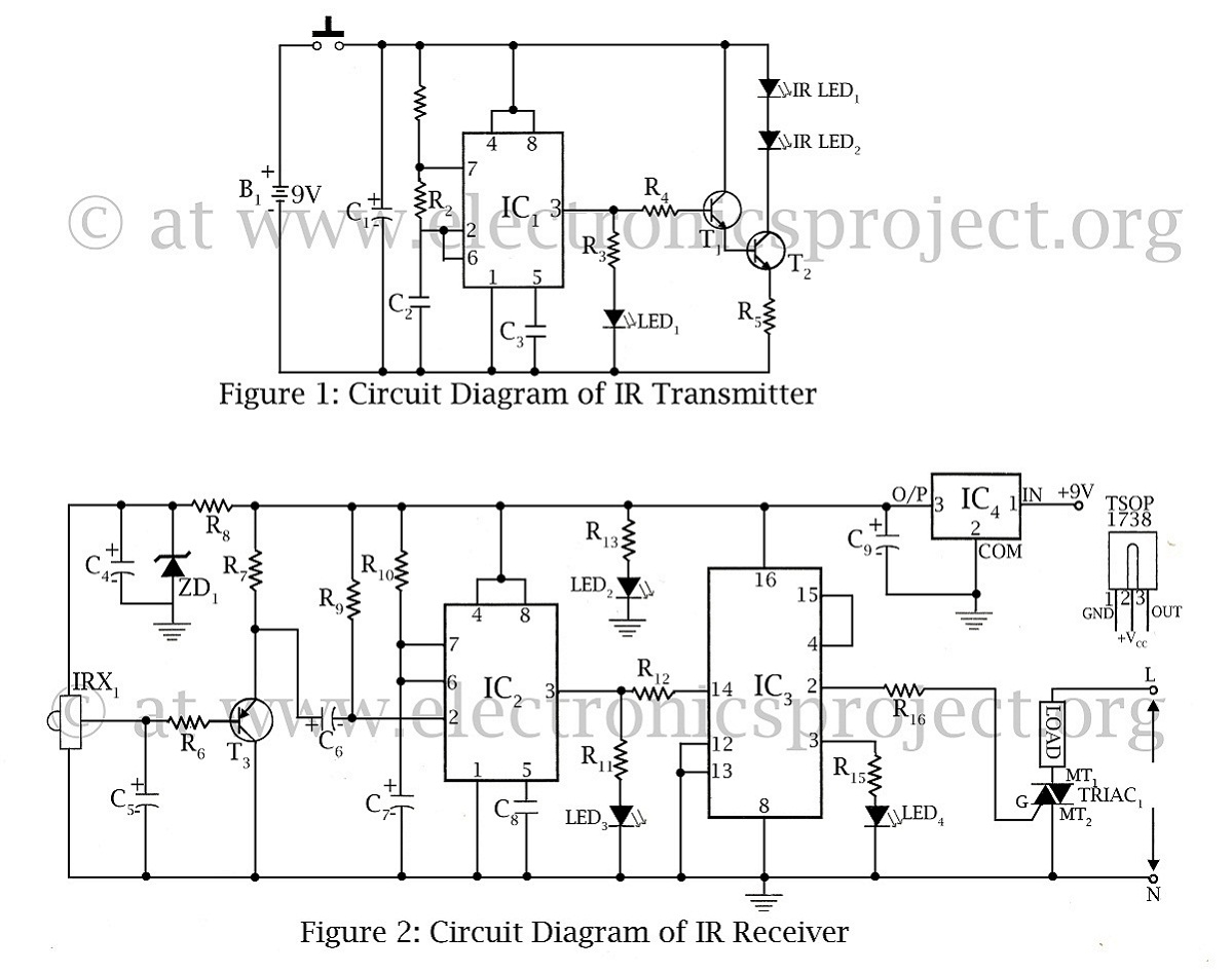
The infrared remote-controlled switch is the second remote-controlled project on this website, utilizing a 555 IC circuit diagram along with a description of the remote-controlled switch. The infrared remote-controlled switch operates using a 555 timer integrated circuit (IC), which is...
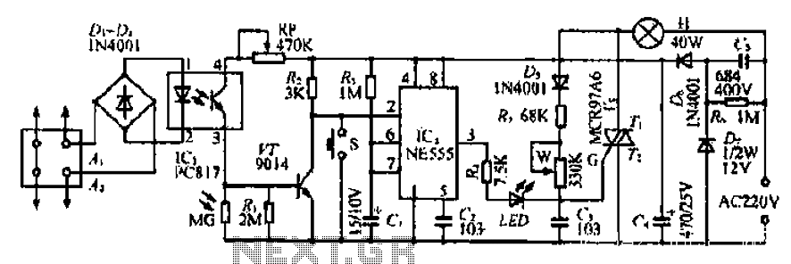
The Ai. A2 series operates with a telephone line, where sound anomalies or off-hook currents activate a light within an arc tube, which in turn triggers a photosensitive MOSFET. This process involves a saturated conduction base voltage that sends...

The sensor must be positioned at an angle of approximately 30 to 45 degrees relative to the ground. This orientation facilitates the drainage of rainwater, preventing accumulation that could trigger the alarm due to water retention on the sensor....
Cuckoo Sound Generator Circuit Schematic. This circuit generates a two-tone effect similar to the cuckoo song. It can be utilized for doorbells or other applications due to a built-in audio amplifier and loudspeaker. The Cuckoo Sound Generator Circuit is designed...
This gated 1-kHz oscillator provides press-to-turn-off functionality, along with waveforms available at the output of pin 3 and across capacitor C1. The gated 1-kHz oscillator circuit is designed to generate a square wave output at a frequency of 1 kHz....
A simple astable timer is constructed using a 555 timer IC. The mark (on) and space (off) durations can be set independently. The timing circuit comprises resistors Ra, Rb, and capacitor Ct. The capacitor Ct charges through resistor Ra,...