
TV Transmitter
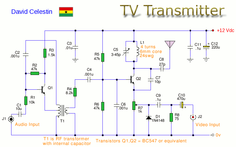
This analogue TV transmitter circuit is designed to provide a comprehensive solution for broadcasting audio and video signals. The core of the transmitter is built around a frequency-modulated audio signal combined with a phase-alternating line (PAL) video signal, ensuring compatibility with specific television standards. The frequency tuning capability, adjustable via capacitor C5, allows for precise channel selection within the 54 to 216 MHz range, which is critical for compliance with local broadcasting regulations.
The circuit architecture includes key components such as transistors Q1 and Q2, which play vital roles in signal generation and amplification. Q1, functioning as an oscillator, ensures that the audio signal is amplified while simultaneously generating the necessary carrier frequency. The use of a transformer (T1) facilitates the creation of the oscillating signal, with its core being adjustable to fine-tune the frequency output.
The modulation process occurs in Q2, where the audio and video signals are mixed to form a composite RF signal. The tank circuit, composed of C5 and L1, is essential for maintaining oscillation at the desired carrier frequency, thereby enabling effective transmission. The inclusion of a preset resistor (R7) allows for dynamic adjustment of the video signal input, which is crucial for optimizing the modulation depth and ensuring clear transmission quality.
For practical implementation, the design accommodates various input sources for both audio and video, making it versatile for different applications. The requirement for a mono audio input simplifies the connection process, while the specification for composite video ensures that the transmitted signal retains its integrity. The choice of antenna, whether a simple wire or a telescopic whip, is appropriate for the frequency range, providing sufficient range for typical broadcasting scenarios.
Overall, this analogue TV transmitter circuit represents a functional and educational project for those interested in exploring the fundamentals of RF transmission and modulation techniques. It is imperative to adhere to local laws and regulations regarding broadcasting to avoid legal complications.This is an Analogue TV Transmitter. Sound modulation is type FM with a 5. 5MHz carrier and video transmission is PAL. Frequency is adjustable via C5 and tunes 54 to 216Mhz with components shown. This is suitable for countries using TV systems B and G. Please Note: This circuit will be illegal to use in many countries, as such, it is displayed here for educational purposes only. Please read the disclaimer on my site. This transmitter circuit uses 5. 5Mhz, FM modulation for sound, and PAL for video modulation. The transmitter is tunable between 54 and 216Mhz. The transmitter is therefore compatible with TV systems B and G, but check transmitter frequencies used, as they are different for each country; see the links at the bottom of the page. The audio is applied via input connector, J1. This can be a phono type, note also that audio must be mono, if a stereo input is used, either use a stereo to mono adapter, or one channel only.
Transistor Q1 acts as an oscillator and amplifier, the primary of T1 and its internal capacitor oscillating at 5. 5Mhz, the transistor itself provides audio gain. Some adjustable of frequency may be obtained by moving the core of T1. T1 should be a 5. 5MHz IFT, available from an old TV or FM radio or available in UK from Jabdog, see link below: The modulated, audio signal, is now passed to Q2, which acts as a modulation and generates the carrier frequency for the transmitter.
C5 and inductor L1 form the tank circuit which oscillate at the carrier frequency. Once trasmitting adjustment of C5, will alter the channel of the transmitted signal. The video signal is fed via input jack J2. The video signal must be composite, e. g. just video and not contain any audio. Suitable inputs from cameras, or video cameras should be ok. Preset R7 allows adjustment of the video signal input, and hence also controls modulation level. Q2 mixes the video input with the sound input to produce a modulated RF video signal containing both audio and video components. Because this transmitter is working at 54to 216MHz then a short length of wire or telescopic whip antenna will work.
Transmitting at higher frequencies, e. g. 546Mhz to 860Mhz requires a different RF transistor and a portable TV antenna to transmit at these frequencies. 🔗 External reference
Related Circuits
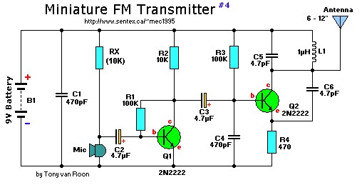
This is a mini FM transmitter designed by Tony van Roon, powered by two transistors. It is straightforward to assemble, and its transmissions can be received on any standard FM radio. The transmitter has an approximate range of 1/4...
L1 is 0.112uH (this tunes to the middle of the FM band, 98 MHz, with VC1 at its centre value of 33pF). L1 is 5 turns of 22 swg enamelled copper wire close-wound on a 5mm (3/16") diameter former....
The circuit was constructed using a few components powered by a 9 V battery for sensing the presence of bugs transmitting within the frequency modulation range. Frequency Modulation (FM) transmits its signal or information over a carrier wave by...
An oscillator can be constructed using an LC (inductor-capacitor) tank circuit. By varying the capacitance of the capacitor in the LC tank circuit, the frequency of the oscillator can be adjusted. An LC tank circuit serves as a fundamental building...
A 200-watt class-E AM transmitter designed for non-sanctioned broadcasting at a frequency of 1710 kHz. The schematic includes a negative peak limiter, an over-modulation indicator, a linear scale directional wattmeter, as well as power supply and antenna circuits. The 200-watt...
Here's PLL FM transmitter circuit from china. This circuit uses the familiar 2SC1971 for final power amplifier stage. The PLL controller of the FM transmitter use SAA1057 and PIC16F628 (download HEX file). More: If want to change the active...
Warning: include(partials/cookie-banner.php): Failed to open stream: Permission denied in /var/www/html/nextgr/view-circuit.php on line 713
Warning: include(): Failed opening 'partials/cookie-banner.php' for inclusion (include_path='.:/usr/share/php') in /var/www/html/nextgr/view-circuit.php on line 713