
Two-channel Analog-to-Digital converter board with USB interface
The interface board designed to connect photovoltaic tubes to a personal computer serves as a crucial component for data acquisition in scientific applications. The board leverages the Texas Instruments PCM2900 chip, which is well-suited for this purpose due to its ability to handle stereo input and its compatibility with USB interfaces. This chip facilitates the conversion of analog signals from the photovoltaic tubes into digital data that can be processed by the computer.
The design of the interface board focuses on specific signal properties, ensuring that the system can handle the required voltage levels and sampling rates. With a maximum signal level of 10V and a sampling rate of 1000 samples per second at a 10-bit depth, the board is capable of accurately capturing the nuances of the output from the photovoltaic tubes.
The decision to omit capacitors C9 and C10 was made to accommodate the direct current (DC) nature of the input signal, which simplifies the circuit design. The incorporation of potentiometers allows for fine adjustments to the signal, enabling optimal performance and calibration of the system. This flexibility is essential for achieving accurate measurements and ensuring that the data collected reflects the true output of the photovoltaic tubes.
Once the assembly is complete, the board's integration with a Windows XP PC is straightforward. The recognition of the board by the operating system as a "USB HID," "USB Audio device," and "USB Composite device" indicates successful communication between the hardware and software. Specifying a new source for sound recording is the final step in configuring the system for data acquisition, allowing the user to begin collecting and analyzing measurements from the photovoltaic tubes effectively.
Overall, this interface board represents a practical and efficient solution for connecting scientific measurement devices to personal computers, facilitating research and data collection in various applications.build an interface board to connect some scientific equipment (for me, a pair of photovoltaic tubes) to a personal computer to acquire measurements results. Signal properties were following: two channels with a common ground, 1 second of acquisition time, max 10V signal level.
Desired digitizing properties were about 1000 samples per acquisition, 10 bit depth. The most attractive and cheap solution is to use a PC sound card as an ADC converter. However, most of laptop computers have only mono low-level microphone input onboard. After a careful research, a Texas Instruments PCM2900 chip [1] was chosen as a proper converter (fig. 1). It has a stereo I/O (only input is used in this project), USB interface and MS Windows drivers already shipped with an OS.
A reference board design from TI was used (fig. 2). One can easily found it in the data sheet [2]. Output circuits were removed, and proper capacitors selected. C9 and C10 capacitors were removed as input signal have zero frequency (DC). Instead, a couple of potentiometers (5K and 10K) were placed to do fine board tuning. After an assembly has been finished, the board was plugged onto my PC (Windows XP): Check the "USB HID", "USB Audio device" and "USB Composite device". Also I had to specify a new source for sound recording. 🔗 External reference
Related Circuits
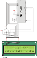
This project involves a USB interface for an alphanumeric LCD display, such as the 4x20 model, which can be controlled using the LCD Smartie program. The USB interface is implemented with the PIC18F2550 microcontroller and utilizes USB LCD modules....
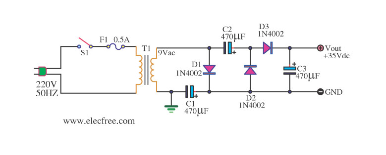
Simple AC to DC converter 9VAC to 35VDC. This is a basic example of an AC to DC converter model designed to be straightforward. It modifies 9VAC input to produce 35VDC output, depending on various factors. The AC to DC...
The circuit below is a DC to DC converter using a standard 12 VAC center tapped power transformer wired as a blocking oscillator. The circuit is not very efficient but will produce a high voltage usable for low power...
The 2x16 Parallel LCD is an 8-bit or 4-bit parallel interfaced LCD. This unit allows the user to display text, numerical data, and custom-created characters. The LCD utilizes the HD44780 series LCD driver from Hitachi or an equivalent controller....
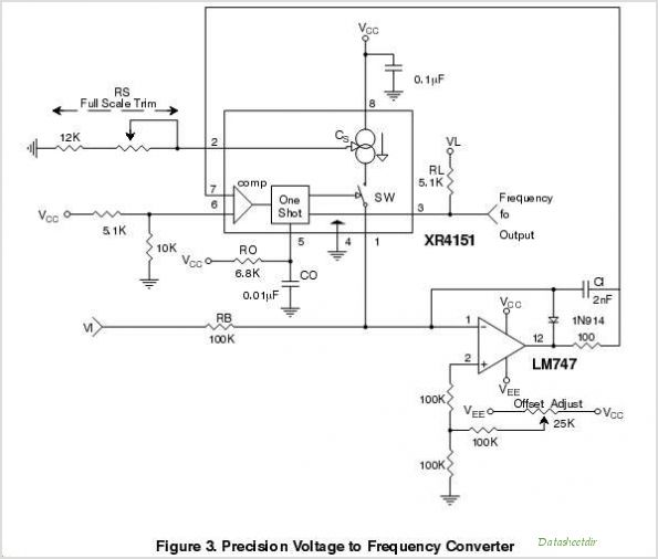
The purpose of this application note is to present an example circuit illustrating the operation of the XR-T5683 device at a data rate of 10.1 Mbps. This note includes the results of measurements taken on the XR-T5683 at this...
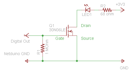
The process of driving an LED involves using a Power MOSFET to control the LED's state (On and Off) via a digital signal. This guide provides a step-by-step approach to wiring the circuit on a breadboard, which serves as...