
12V DC to 85V DC Converter
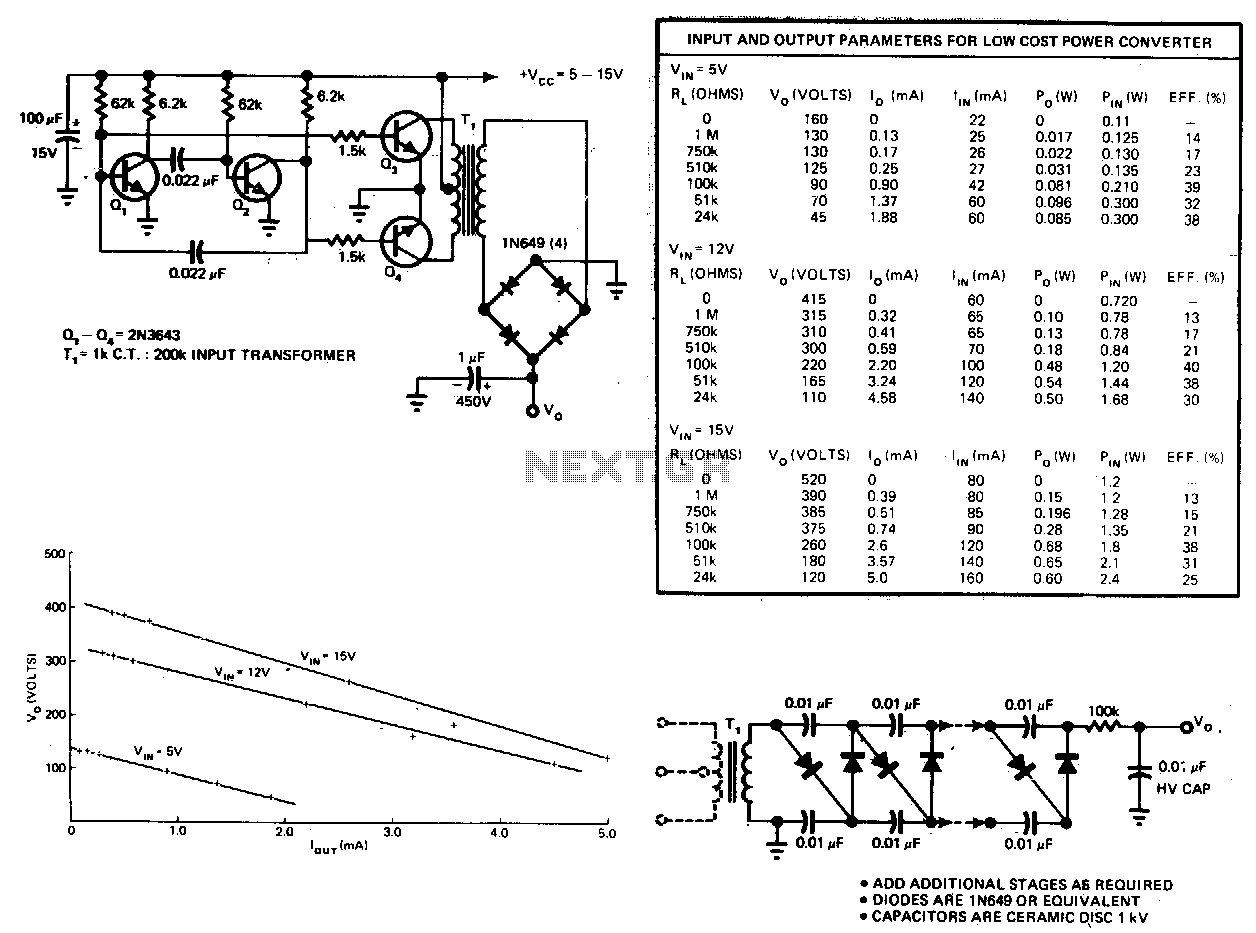
The described circuit functions as a DC to DC converter utilizing a center-tapped 12 VAC transformer configured in a blocking oscillator arrangement. This setup is designed to convert a lower DC voltage into a higher AC voltage, which is then rectified and further increased using a voltage tripler circuit. The blocking oscillator achieves oscillation through a feedback mechanism that allows the transformer to alternately energize and de-energize, generating a pulsed output.
In this circuit, the 12 VAC transformer is pivotal as it steps up the input DC voltage, which is typically derived from 'D' alkaline batteries. The center-tapped design allows for the generation of two equal voltages from the center tap to each end of the winding, facilitating the oscillation process. The output from the transformer is then fed into a voltage tripler, which consists of three capacitors and three diodes arranged to increase the voltage further. The diodes rectify the AC output from the transformer, while the capacitors store and charge the voltage, effectively tripling the output voltage level.
The circuit's efficiency is noted to be low, which is a common characteristic of blocking oscillators; however, it is adequate for low power applications where high voltage is required. The current draw is approximately 40 milliamps, allowing the circuit to operate for an extended duration, estimated at around 200 hours, on a pair of 'D' alkaline batteries. Adjustments to the circuit can be made to increase the output voltage; for instance, reducing the resistance of the 4.7K bias resistor will allow for greater oscillation frequency and, consequently, higher voltage output.
This circuit is particularly useful in applications where a compact, low-power high-voltage source is necessary, such as in gas tube lighting or small ionization devices. Proper attention should be given to component ratings, especially for the diodes and capacitors used in the voltage tripler, to ensure they can handle the elevated voltages produced during operation.The circuit below is a DC to DC converter using a standard 12 VAC center tapped power transformer wired as a blocking oscillator. The circuit is not very efficient but will produce a high voltage usable for low power applications. The input battery voltage is raised by a factor of 10 across the transformer and further raised by a voltage tripler consisting of three capacitors and diodes connected to the high voltage side of the transformer.
The circuit draws about 40 milliamps and should operate for about 200 hours on a couple of 'D' alkaline batteries. Higher voltages can be obtained by reducing the 4.7K bias resistor. 🔗 External reference
Related Circuits
This circuit consists of an astable multivibrator driving a push-pull pair of transistors into the transformer primary. The multivibrator frequency should equal around 1 or 2 kHz. For higher DC voltages, voltage multipliers on the secondary circuit have been...
A low-power converter designed to derive a higher voltage from a main system rail in an on-board application. The operating frequency with the transformer depicted is 250 kHz. Z1 functions as a dissipative voltage regulator for the output and...
The listed currents represent maximum values, and the actual current consumption will vary based on the circuit's operation. This precludes the simple use of a resistor in series to reduce voltage from 12 volts to 9 volts for powering...
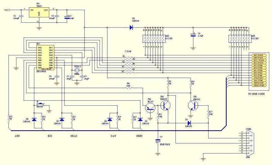
This adaptor will capture plots or prints of your GPIB instrument to your PC through the serial port. It fills the need of anybody who has a test instrument with the GPIB port and likes to get the screen...

This circuit can be connected to any existing calculator battery using a push-on automatic switch, allowing it to function as a stopwatch while the calculator is not in use. The circuit utilizes a 555 timer configured in monostable mode to...
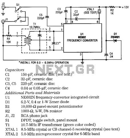
The NE602 chip, U1, contains oscillator and mixer stages. The mixer combines the oscillator signal with the input RF signal to produce signals whose frequencies are the sum and difference of the input frequencies. For example, an 8.5-MHz oscillator...
Warning: include(partials/cookie-banner.php): Failed to open stream: Permission denied in /var/www/html/nextgr/view-circuit.php on line 713
Warning: include(): Failed opening 'partials/cookie-banner.php' for inclusion (include_path='.:/usr/share/php') in /var/www/html/nextgr/view-circuit.php on line 713