
two Colpitts oscillators
The NPN Colpitts oscillator is a type of electronic oscillator that utilizes an NPN transistor as the active component to generate oscillations. This oscillator is characterized by its use of a tank circuit, which typically consists of a combination of capacitors and an inductor. The Colpitts configuration employs two capacitors in series to form a voltage divider, with the inductor connected to the collector of the transistor.
In operation, the transistor amplifies the signal, and the feedback from the tank circuit sustains the oscillation. The frequency of oscillation is primarily determined by the values of the capacitors and the inductor according to the formula:
\[ f = \frac{1}{2\pi\sqrt{L \cdot C_{total}}} \]
where \( C_{total} \) is the equivalent capacitance of the two capacitors in series. The stability and frequency response of the Colpitts oscillator can be influenced by the selection of components, and it is commonly used in applications such as RF signal generation and frequency modulation.
The schematic for a typical NPN Colpitts oscillator would include the NPN transistor, the two capacitors forming the feedback network, the inductor, a power supply, and additional components such as resistors for biasing the transistor. Properly designing the circuit requires careful consideration of the component values to achieve the desired oscillation frequency and amplitude.Hello, I have queastion about type of the osclator I found on wikipedia here: File:NPN Colpitts oscillator collector coil.png - Wikipedia, the free.. 🔗 External reference
Related Circuits
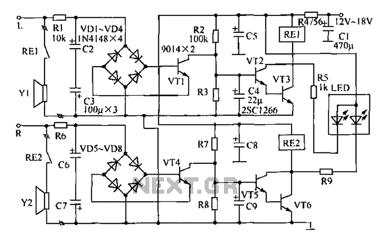
The speaker protection circuitry is designed for independent operation of the left and right channels. The left channel is exemplified by components R2, C4, and the VT2, VT3 configuration, which includes a start delay circuit to prevent power surges...
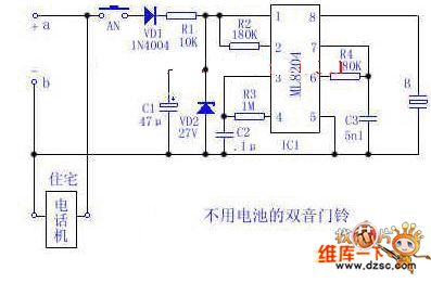
Utilize the 48V (60V) DC feedback electric current supplied by the phone feedback line as the operational energy source for the electronic doorbell, which is highly economical and practical. This document introduces a two-tone doorbell circuit that operates without...
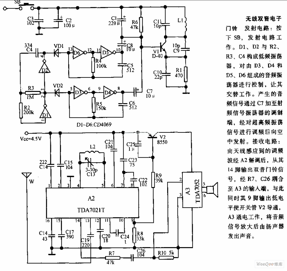
The transmitter circuit is activated by pressing the SB button. Components D1, D2, R2, R3, and C4 form a low-frequency oscillator that controls an audio oscillator made up of D3, D4, D5, and D6, allowing them to operate alternately....
This result places the oscillator within the UK FM Band, which ranges from 87.5 to 108 MHz. If L1 is equipped with an adjustable ferrite core, its inductance can be modified, allowing for fine tuning. If L1 consists of...
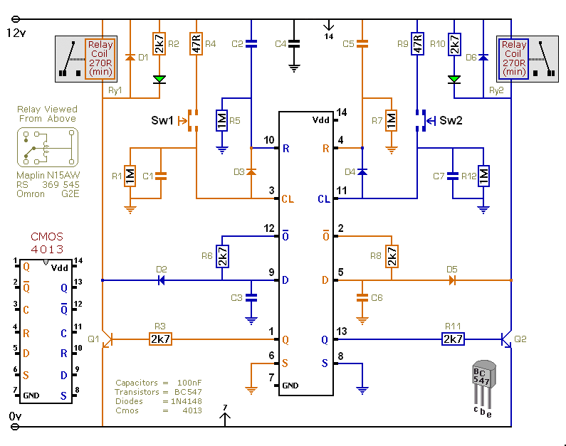
This versatile circuit offers a selection of different switching modes. It can function as two entirely separate toggle switches, with each push button successively energizing and de-energizing its corresponding relay. Alternatively, the two switches can be interconnected with diodes...

This circuit is designed for children's entertainment and can be installed on bicycles, battery-powered cars, motorcycles, as well as various models, games, and toys. When switch SW1 is positioned as indicated in the circuit diagram, it generates the typical...
Warning: include(partials/cookie-banner.php): Failed to open stream: Permission denied in /var/www/html/nextgr/view-circuit.php on line 713
Warning: include(): Failed opening 'partials/cookie-banner.php' for inclusion (include_path='.:/usr/share/php') in /var/www/html/nextgr/view-circuit.php on line 713