
2Y- connection two-speed motor contactor control circuit of the four
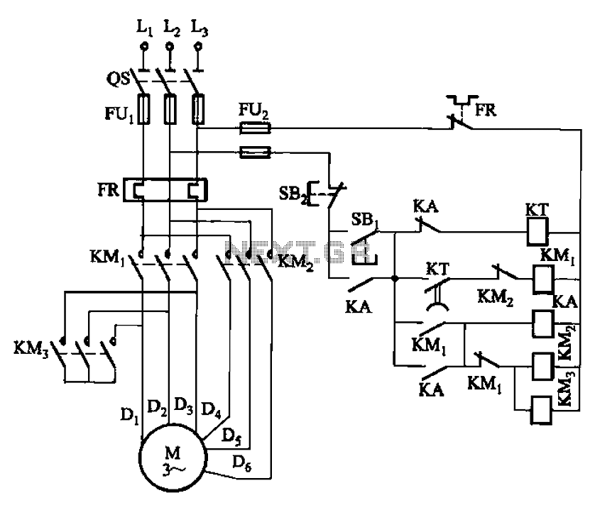
The circuit operates by initially applying a lower voltage to the motor, allowing for a gradual increase in speed. This is particularly useful in applications where sudden starts can cause mechanical stress or where a gradual ramp-up is necessary for operational safety. The shaped connection serves to limit the initial current, ensuring that the motor does not draw excessive power at start-up.
Once the motor reaches a predetermined low-speed threshold, the time relay KT activates, allowing the circuit to switch to the high-speed operation mode. The timing of this transition can be fine-tuned according to the specific requirements of the application, providing flexibility in operational performance.
The low-speed start button SBi serves as a manual control mechanism, enabling the operator to initiate the motor's start-up process at a low speed. This feature is particularly beneficial in scenarios where precise control over the motor's acceleration is necessary, such as in conveyor systems or pumps where load conditions may vary.
Overall, the design of this circuit not only enhances the longevity of the motor by preventing abrupt starts but also optimizes the operational efficiency by allowing for adjustable acceleration times. The integration of these components ensures that the motor operates smoothly across its speed range, thereby improving reliability and performance in various applications. Circuit shown in Figure 3-99. The low start-up circuit to the motor ( shaped connection), then automatically accelerated speed into high speed (2Y-connector) operation. Start f rom low to high speed running interval can be adjusted time relay KT. Figure, SBi low speed start button.
Related Circuits
The circuit diagram for the automatic control of drinking fountains is presented below. The automatic control circuit for drinking fountains typically employs a combination of sensors and control elements to manage the operation of the fountain efficiently. The main components...
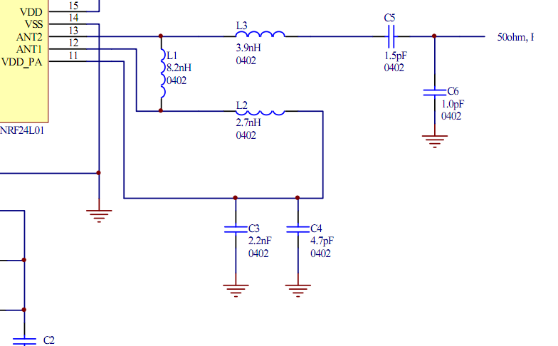
Place the transceiver and the chip antenna very close together, eliminating the need for a 50-ohm transmission line. If this is the case, can the two matching circuits be merged into one to reduce the component count? To create an...
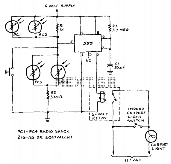
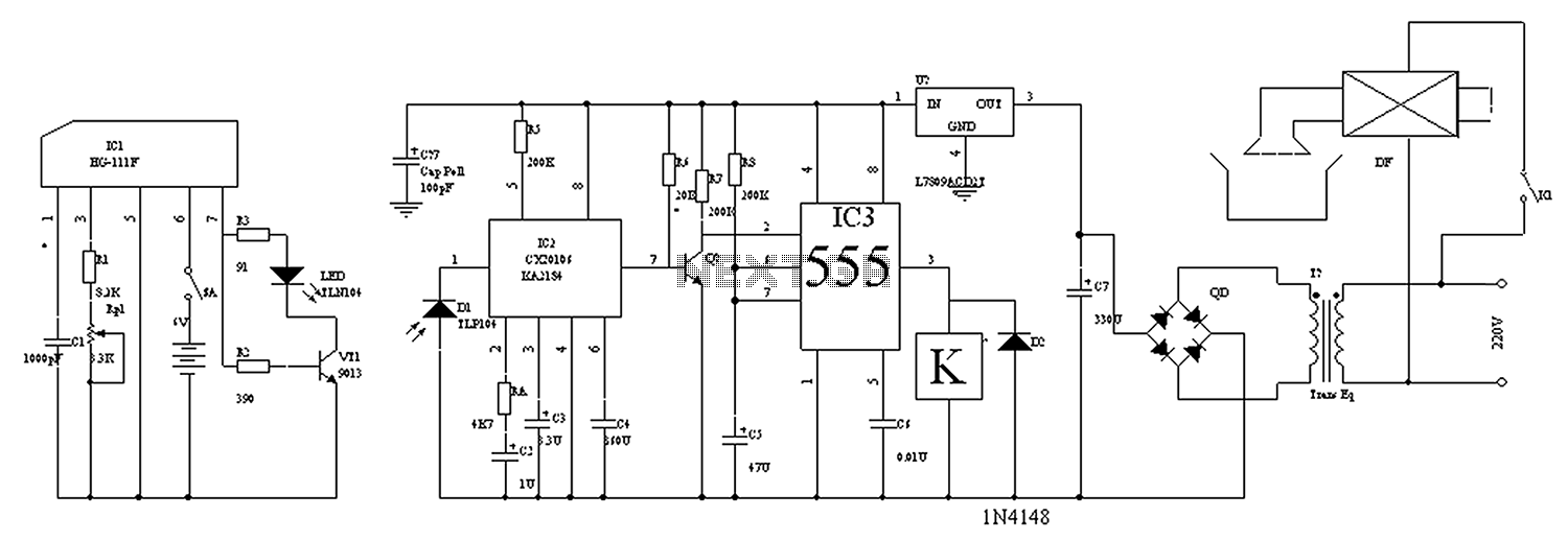
A 555 timer integrated circuit (IC) functions in one-shot mode, triggered by light exposure to photoresistors. These photoresistors typically exhibit a resistance in the range of several megohms, which decreases to several hundred ohms under light conditions, allowing current...
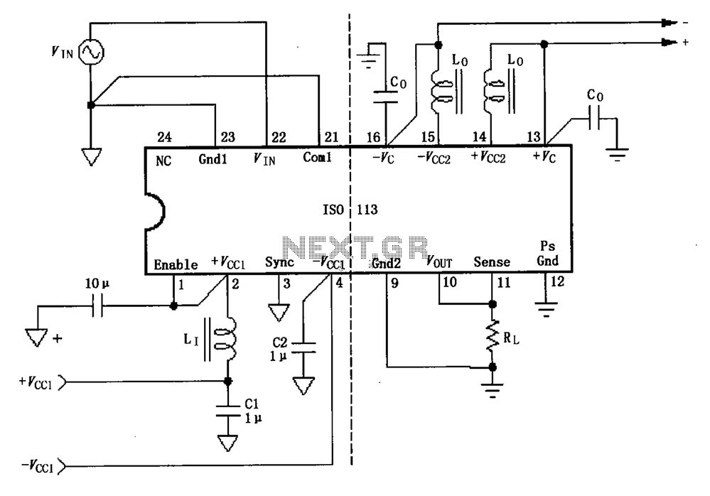
The basic connection circuit for the ISO113 signal and power supply is illustrated. Each power supply terminal must include a bypass filter. If the output current from the isolated power supply exceeds 15mA, it is advisable to utilize an...

Tone controls are often discouraged in high-end audio systems. However, one might argue that a high-end audio cable functions similarly to a high-end tone control. It is possible to purchase or... Tone controls in audio systems serve to adjust the...
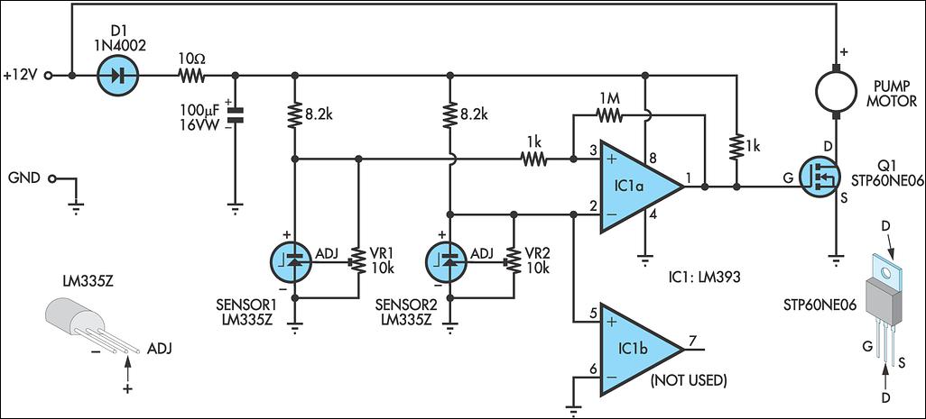
A solar water heating pump controller is an essential component in most solar water heating systems, whether DIY or commercially produced. Its primary function is to activate the pump when the fluid in the solar panel is at a...