
TWO QUADRANT
The described circuit employs a bipolar digital multiplier that utilizes an offset binary-coded digital input to control the output polarity. This configuration allows for precise manipulation of the output signal, which is particularly useful in applications requiring accurate signal processing and conversion.
The core component of this circuit is the Precision Monolithics DAC-08, a highly regarded digital-to-analog converter known for its precision and reliability. The DAC-08 converts the digital input signal into an analog output, which is then processed by the OP-02 operational amplifier. The OP-02 is selected for its low noise and high-performance characteristics, enhancing the overall fidelity of the output signal.
The output of the circuit is designed to be symmetrical about the ground, meaning that it can produce both positive and negative voltage swings relative to the ground reference. This feature is essential in various signal processing applications, as it allows for the representation of bipolar signals, which are common in many electronic systems.
In summary, this bipolar digital multiplier circuit effectively translates digital inputs into precise analog outputs while maintaining symmetry about the ground, making it suitable for a wide range of applications in electronic signal processing. The combination of the DAC-08 and the OP-02 op-amp ensures high performance and accuracy in the generated output signals.Bipolar digital multiplier has output polarity controlled by offset-binary-coded digital input word. Precision Monolithics DAC-08 D/A converter drives OP-02 opamp. 0utput is symmetrical about ground. -J. Schoeff and D. Soderquist, Differential and Multiplying Digital to Analog Converter Applications, Precision Monolithics, Santa Clara, CA, 1976, AN -19, p2. 🔗 External reference
Related Circuits
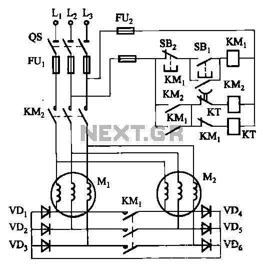
The circuit depicted in Figure 3-157 is designed for motors with a capacity of no more than 11 kW, requiring precise stopping capabilities. Upon shutdown, contact KMi releases, and the motor stator windings are configured into a three-phase rectifier...
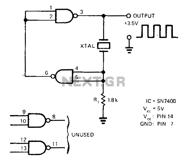
A SN7400 quartz crystal and a resistor provide a square-wave output of approximately 3.5 V. The circuit operates reliably at frequencies from 120 kHz to 4 MHz. The circuit utilizes a SN7400 integrated circuit, which is a quad two-input NAND...
This circuit is designed for children's entertainment and is suitable for installation on bicycles, battery-powered cars, motorcycles, as well as models and other games. When switch SW1 is positioned as indicated in the circuit diagram, it generates the typical...
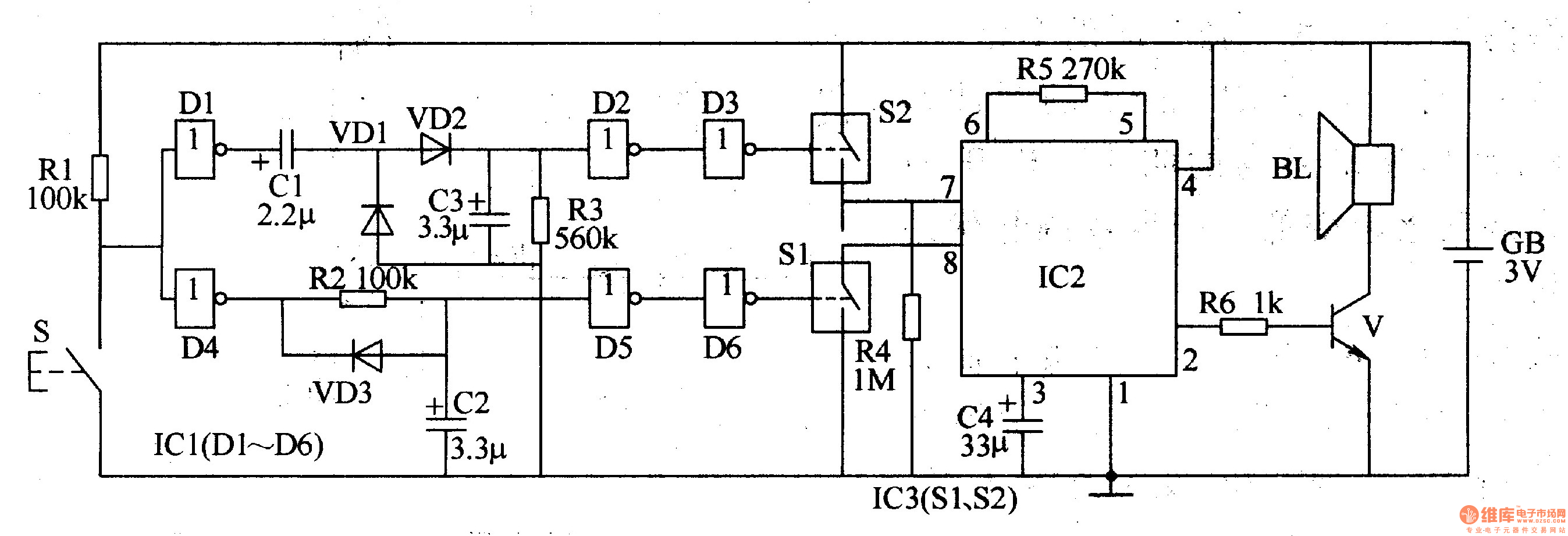
The two-tone electronic doorbell circuit comprises a trigger control circuit and a doorbell generating circuit, as illustrated in Figure 3-108. The trigger control circuit includes a doorbell button (S), resistors (R1-R3), electrical components (C1-C3), diodes (VD1-VD3), six NOT gate...
A functional AM transmitter has been completed, primarily based on Phil's Li'l 7 Transmitter design. Achieving oscillation in LC-based transmitters can be challenging without the correct combination of tubes and coils. This transmitter utilizes a 6J5 and a 6SA7...
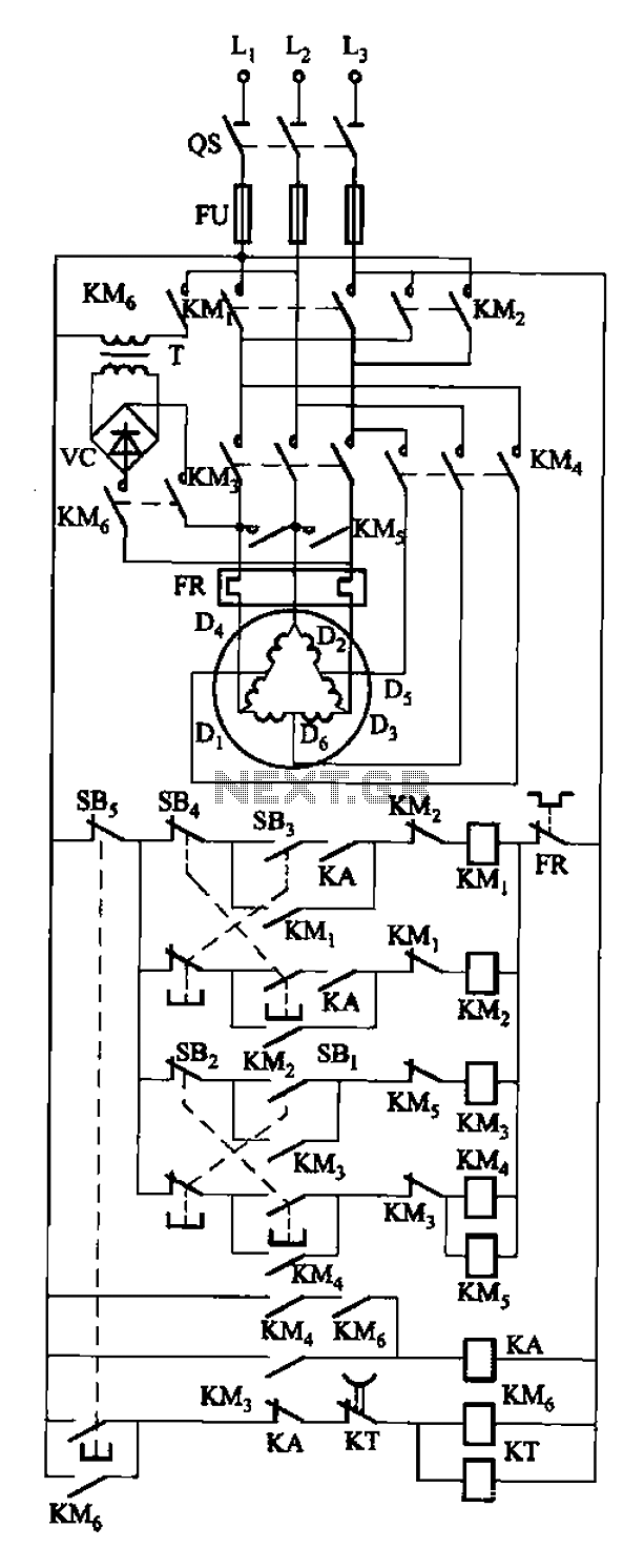
The circuit depicted in Figure 3-108 includes various control buttons: SB3 for the forward button, SI for the reverse button, SBi as the low start button, SB2 for the speed start button, and SBs for the stop button. KMs...