
One-IC two-tones Siren
This circuit incorporates a sound generation mechanism that utilizes integrated circuits (ICs) to produce various sound effects. The primary components include two sets of operational amplifiers (IC1A, IC1B) that create the dual-tone sound reminiscent of emergency vehicles. The sound output is modulated by the configuration of the capacitors and resistors, which define the frequency and amplitude of the tones produced.
The implementation of switch SW1 allows the user to toggle between two distinct sound profiles: a police/fire siren and an old-fashioned siren. The transition between these sounds is facilitated by the oscillators IC1C and IC1D, which are activated by the push button P1. This feature provides an engaging interactive element for children, enabling them to control the sound output.
The loudspeaker selection is crucial for sound quality. It is recommended to use a loudspeaker with adequate power handling capabilities to ensure that the output is both realistic and loud enough for outdoor use. Proper casing of the loudspeaker will help in amplifying the sound and preventing distortion.
To customize the sound further, users can experiment with the values of capacitors C1, C2, C5, and C6, as well as the associated resistors. Adjustments to these components will allow for fine-tuning of the pitch and duration of the generated tones, providing a versatile audio experience.
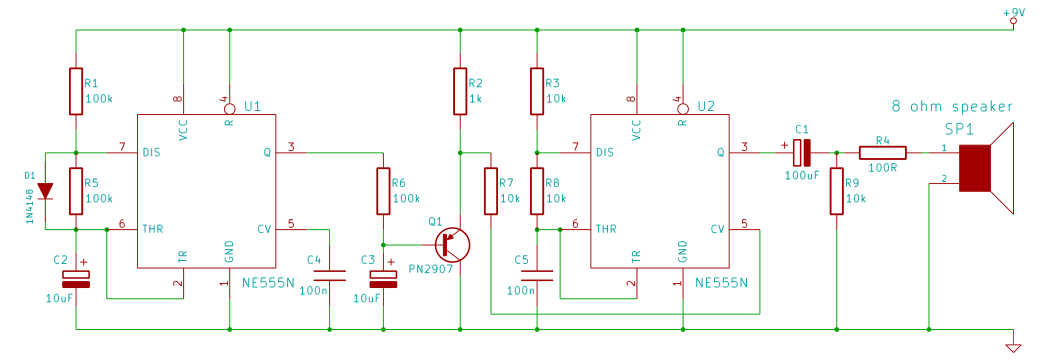
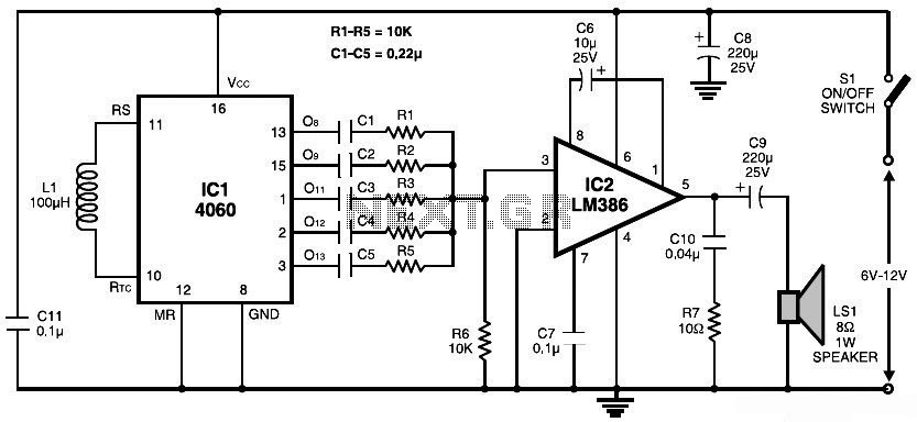
The circuit's design prioritizes low power consumption, making it suitable for battery-operated applications. By not incorporating a dedicated power switch, the circuit can remain in a low-power state when not actively generating sound, ensuring efficient energy use. This feature is particularly beneficial for portable devices where battery longevity is a concern.This circuit is intended for children fun, and is suitable to be installed on bicycles, battery powered cars and motorcycles, but also in models and other games. With SW1 positioned as shown in the circuit diagram it reproduces the typical dual tone sound of Police or Fire-brigade cars, by the oscillation of IC1A and IC1B gates.
With SW1 in the ot her position, the old siren sound increasing in frequency and then slowly decreasing is reproduced, by pushing on P1 that starts oscillation in IC1C and IC1D. The loudspeaker, driven by Q1, should be of reasonable dimensions and well encased, in order to obtain a more realistic and louder output.
Tone and period of the sound oscillations can be varied changing the values of C1, C2, C5, C6 and/or associated resistors. There is no power switch: leave SW1 in the low position (old-type siren) and the circuit consumption will be negligible.
🔗 External reference
Related Circuits
This tutorial outlines the construction of a wailing siren that produces a tone with varying pitch. The circuit incorporates two 555 integrated circuits (ICs) and a loudspeaker. The wailing siren circuit is designed to create an audio effect that simulates...
This circuit provides a good siren noise suitable for warding off robot-predators! Change the pitch by adjusting R2, and R5. More: all resistors are 5 or 10 percent tolerance, 1/4-watt all capacitors are 10 percent tolerance, rated 35 volts...

The operation of the circuit is divided into three parts: low-frequency production, high-frequency manufacturing, and low-frequency extension. The low-frequency signal is generated from IC1, which is connected to an astable multivibrator circuit. The frequency is determined by the resistor...
The circuit presented generates a smooth, piercing, wailing siren with minimal components. Additionally, three spare gates of the hex inverter IC1 are available, allowing the possibility of creating a cacophony by operating two sirens from the same integrated circuit....
This document presents a simple schematic of a multitone siren alarm circuit. The multitone siren is effective for reverse horns, burglar alarms, and various other applications. It generates five distinct audio tones, making it significantly more attention-grabbing than a...
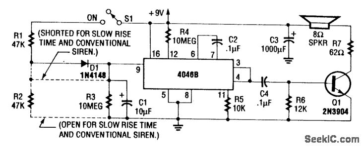
For a normal wailing tone, short D1 and leave R2 open. To achieve a fast rise and slow fall in frequency, include both D1 and R2. Utilizing a CD4046B with a diode-RC network as illustrated generates a siren tone...