
Two-speed motor stator winding 2Y-2Y connection
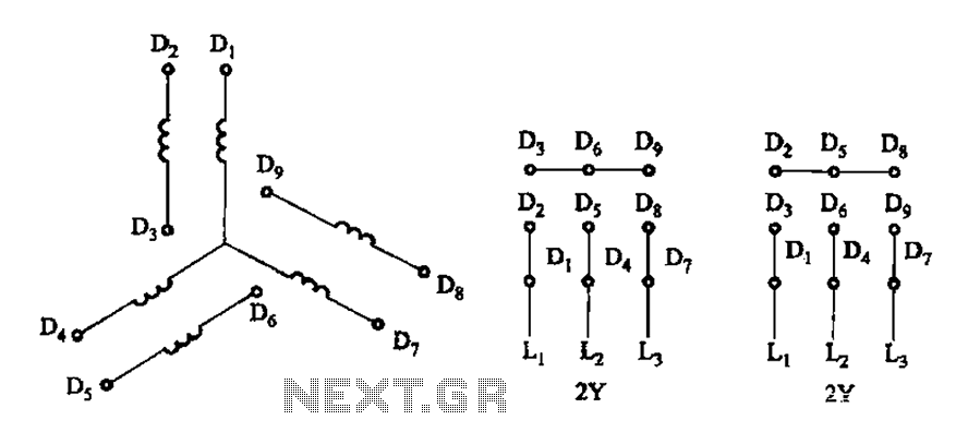
The two-speed motor stator wiring diagram is essential for understanding the configuration and operation of the motor. In this setup, the stator windings are connected in a 2Y (two-phase star) arrangement, which allows for the motor to operate at two different speeds. The diagram typically indicates the various terminals of the stator windings, showing how they connect to the power supply and the control circuitry.
In a 2Y connection, each phase of the motor is connected to a common neutral point, which reduces the voltage across each winding, thus allowing for a more efficient operation at lower speeds. The two-speed capability is often achieved by connecting different sets of windings to the power source, enabling the motor to switch between high and low speed based on the control signals received.
The diagram must clearly label the terminals, including the start and end points of each winding, as well as any additional components such as capacitors or relays that may be involved in the switching mechanism. It is crucial to ensure that the connections are made correctly to prevent any electrical faults or inefficiencies in the motor's operation. Proper understanding of this wiring diagram is vital for technicians and engineers engaged in the maintenance and troubleshooting of two-speed motors. As shown in Figure 3-105 2Y/2Y-connected two-speed motor stator windings lead wiring diagram.
Related Circuits
Stepper motors consist of a permanent magnet rotating shaft, known as the rotor, and electromagnets on the stationary part that surrounds the motor, referred to as the stator. One complete rotation of a stepper motor is illustrated. At position...
Traditional control methods for fan power equipment involve manual or relay control, which often leads to issues of poor reliability and flexibility. For instance, when the motor capacity is large, the startup process can be prolonged, resulting in high...
During the process of organizing computer files, a schematic was discovered that was utilized in the initial phase of USB LED Matrix development. It is believed that this schematic could be beneficial to others. The schematic in question pertains to...
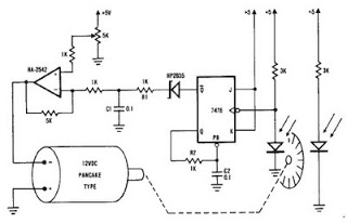
A simple encoder circuit for a DC motor can be constructed using the provided circuit diagram. The system includes the HA-2542 operational amplifier, a small 12 V DC motor, and a position encoder. During operation, the encoder generates a...
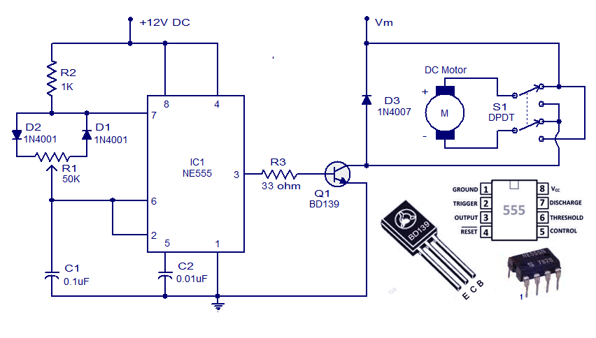
This weblog discusses electronic circuit schematics, PCB design, DIY kits, and electronic project diagrams. A simple DC motor controller circuit utilizing the NE555 timer is presented. Several DC motor speed control circuits are explored, with this being the first...
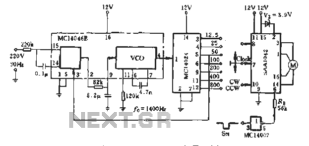
A typical application example is presented, demonstrating the SAA1042 12V stepper motor drive configuration. The phase winding current is set at 200mA. According to RB Figure 5-10, a resistor value of RE = 56kΩ is selected. This resistor is...
Warning: include(partials/cookie-banner.php): Failed to open stream: Permission denied in /var/www/html/nextgr/view-circuit.php on line 713
Warning: include(): Failed opening 'partials/cookie-banner.php' for inclusion (include_path='.:/usr/share/php') in /var/www/html/nextgr/view-circuit.php on line 713