
Function Generator Circuit
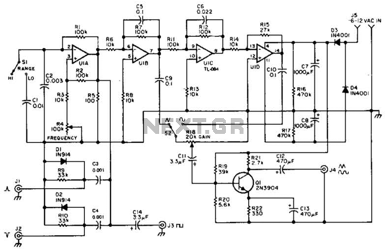
The function generator circuit utilizes a quad operational amplifier (op-amp) configuration, which is essential for generating various waveform outputs. The op-amp U1A is configured to produce a square wave signal. This square wave is then directed to output terminal J8, where it can be utilized for further processing or testing.
To obtain pulse outputs, the circuit differentiates the square wave signal. This differentiation is achieved through additional circuitry connected to the outputs J1 and J2. These outputs provide sharp pulse signals that can be employed in various applications, such as timing circuits or digital signal processing.
The op-amp U1B is configured as an integrator, which takes the square wave input and generates a triangle wave output. This triangle wave is crucial for the subsequent shaping process that transforms it into a sine wave. The sine wave output is often required in applications such as audio signal generation or analog modulation.
The output stage of the circuit includes Q1, which acts as an output amplifier. This component is responsible for boosting the signal strength of the generated waveforms, ensuring they can drive loads effectively without significant signal degradation. The overall design emphasizes versatility and precision, making it suitable for a wide range of electronic applications. A quad op amp makes up the heart of this function generator. Ul-a generates a square wave, and outputs this to J8. J1 and J2 are pulse outputs obtained by differentiating the square wave. Integrator Ul-b generates a triangle-wave shaper to obtain a sine wave. Ql is an output- amplifier. 🔗 External reference
Related Circuits
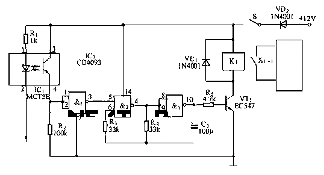
An anti-theft car audio system circuit is depicted, powered by a 12V DC supply from the car battery. Upon closing switch S1, the light-emitting diode in optocoupler IC1 activates, causing the phototransistor to conduct. This results in a high-level...
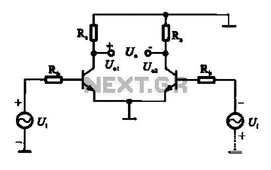
An amplifier circuit is designed to handle an assumed input consisting of two equal and opposite polarity signals, known as a differential mode signal. The two tube collector currents, Ic and IC7, are balanced in such a way that...
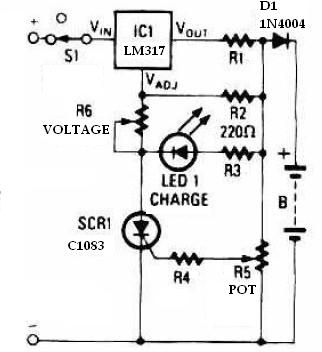
This schematic circuit for a battery charger consists of very few components but operates effectively. When power is applied to the circuit, SCR1 remains off, preventing any bias current from flowing to ground. The LM317 voltage regulator is connected...
This is a mini-sized power amplifier rated at 2 watts OTL that utilizes the LM380 integrated circuit. It serves as a ready-made circuit for audio applications and communication, requiring minimal external equipment. The capacitor C6 can be selected from...
This LED flasher circuit is a classic two-transistor flip-flop. It is a popular circuit often built by beginners in the electronics hobby. The schematic diagram of this well-known LED flasher circuit includes two transistors, two capacitors, four resistors, and...
The industrial fuel oil furnace controller circuit consists of a power supply circuit, a testing and ignition control circuit, and a control implementation circuit, as illustrated in the accompanying diagram. The power supply circuit includes a step-down capacitor (C6),...
Warning: include(partials/cookie-banner.php): Failed to open stream: Permission denied in /var/www/html/nextgr/view-circuit.php on line 713
Warning: include(): Failed opening 'partials/cookie-banner.php' for inclusion (include_path='.:/usr/share/php') in /var/www/html/nextgr/view-circuit.php on line 713