
two wire arduino knight rider
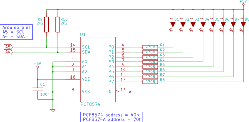
To implement the Knight Rider display using an Arduino and a PCF8574 I/O expander, the circuit design involves connecting the LEDs to the I/O expander, which allows control of multiple outputs while minimizing the number of pins required from the Arduino. The PCF8574 is an 8-bit I/O port expander that communicates with the Arduino via the I2C protocol, utilizing only two pins: SDA (data line) and SCL (clock line).
The schematic includes eight LEDs connected to the output pins of the PCF8574. Each LED should be connected in series with a current-limiting resistor to prevent excessive current flow that could damage the LEDs. The Arduino will send commands to the PCF8574 to turn on and off the LEDs in a sequential pattern, creating the characteristic sweeping effect of the Knight Rider display.
The power supply for the circuit can be derived from the Arduino itself, ensuring that the voltage levels are compatible with the PCF8574 and the LEDs, typically 5V. The I2C bus should also include pull-up resistors on the SDA and SCL lines to ensure proper communication between the Arduino and the PCF8574.
Programming the Arduino involves initializing the I2C communication and defining the output pins for the LEDs. A loop can be created to turn on each LED in sequence, followed by turning them off in reverse order, creating a back-and-forth motion. The timing of the LED transitions can be adjusted to achieve the desired speed of the sweeping effect.
This setup not only demonstrates effective use of the PCF8574 for expanding I/O capabilities but also provides a visually engaging project that illustrates the principles of LED control and I2C communication in microcontroller applications.Connect eight LEDs to an Arduino and make a Knight Rider display using only two Arduino pins in this tutorial. This is made possible by using a PCF8574 I/O expander IC.. 🔗 External reference
Related Circuits
Home appliances are typically controlled using switches, sensors, and similar devices. However, physical interaction with switches can pose risks, particularly in the event of short circuits. The circuit presented here eliminates the need for physical contact to operate the...
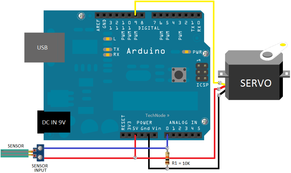
Charge a simple servo that only has + and - pins. Typically, the - pin is connected to ground, while the + pin is connected to a digital output from an Arduino. This setup works, but the servo operates...
The analog to digital sketches have been extensively covered using various components. To progress to more complex circuits and concepts, it is essential to understand these simpler ones. This tutorial will not delve as deeply as others due to...
In the first circuit, the BC548 transistor is configured as a Colpitts oscillator, with the frequency being adjusted through the use of a crystal. A high-quality crystal will produce high-frequency oscillations, and the output at the collector is rectified...

The following circuit illustrates the Ford Probe Single Wire Door Alarm System. This Single Door Locking Wire manages both LOCK and UNLOCK functions, indicating that the pulse wires must be connected to the same vehicle wire. The system primarily...
Part fill valves are commonly utilized in rainwater tanks. The valve activates when the water level in the tank drops to a low position. Part fill valves play a crucial role in the management of water levels in rainwater harvesting...