
Two-wire RTD connection circuit diagram XTR108
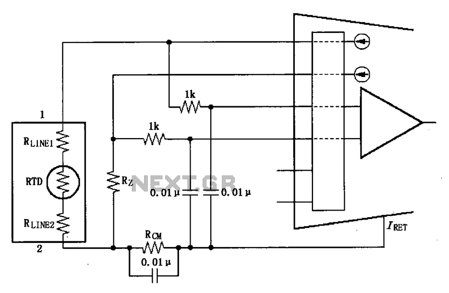
The described circuit addresses the challenges posed by RF interference in current loop transmission systems, particularly when using the XTR108 for sensor applications. The XTR108 is a precision current transmitter, often used in applications involving resistance temperature detectors (RTDs). Given its sensitivity, any RF noise can significantly affect its performance and accuracy.
In this setup, the 0.01 µF bypass capacitor acts as a high-frequency filter, effectively shunting unwanted RF energy to ground, thereby protecting the input stage of the XTR108. The placement of this capacitor is critical; it should be connected as close as possible to the input terminals of the XTR108 to ensure maximum effectiveness. The IRET point, which is typically the return path for the current loop, must be carefully considered, as it is not at ground potential but serves as the reference for the transmitter.
Additionally, the use of another 0.01 µF capacitor at the VLOOP connection helps to stabilize the output signal by filtering out high-frequency noise that may couple into the loop. This capacitor should also be positioned close to the output terminal to minimize inductive effects that could degrade the performance.
Overall, this configuration enhances the reliability of the XTR108 in noisy environments by ensuring that both the input and output stages are adequately filtered against RF interference, thus preserving the integrity of the signal transmitted from the sensor. Proper attention to component placement and values is crucial for achieving optimal performance in industrial and sensitive measurement applications. As shown, the long wire current loop transmission will be introduced radio frequency (RF) interference, RF energy can cause sensitive XTR108 input errors, performance in an uns table loop current or input line current. If the RTD sensor in the distance, in the XTR108 input will introduce interference. If the transmitter and sensor short connections, the more interference from the current loop cable. The solution is applied at the input 0.01 F bypass capacitor filter, to reduce or eliminate the interference. Connect these common points with IRET end of the bypass capacitor, although IRET ends of the DC voltage is not zero, but it is the transmitter of ground.
In addition, VLOOP with a 0.01 F capacitor Io indirect end, the output will help to minimize interference.
Related Circuits
The oscillator employs a fundamental quartz crystal, capable of achieving an oscillation frequency of up to 10 MHz. The oscillator circuit is calibrated to the resonant frequency of the crystal. A capacitor, designated as C, with a value of...

I constructed this voltage regulator to power my two way mobile radio from the car cigarette lighter circuit. It has many other uses and the voltage can easily be adjusted by the use of a potentiometer. The voltage regulator...
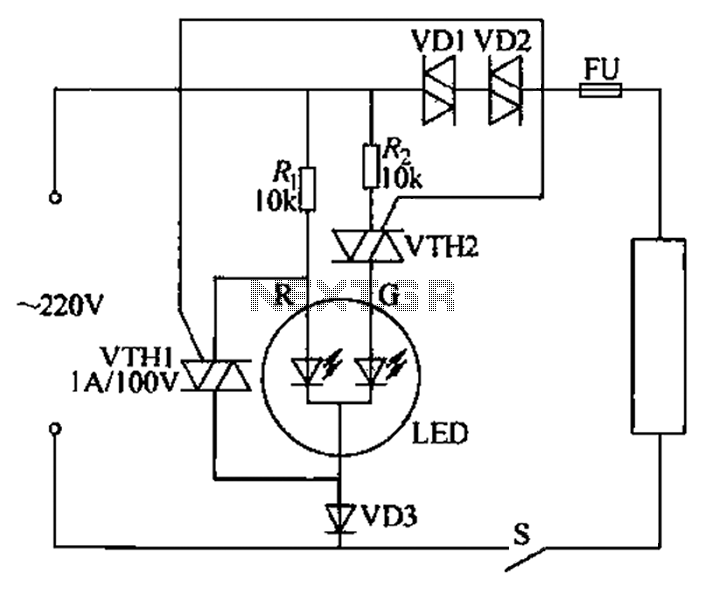
Color light-emitting diodes with different colors can indicate the operational status of electrical equipment, as illustrated in the accompanying figure. The red light-emitting diode (LED) R emits red light when energized, indicating that the 220V power supply is functioning...
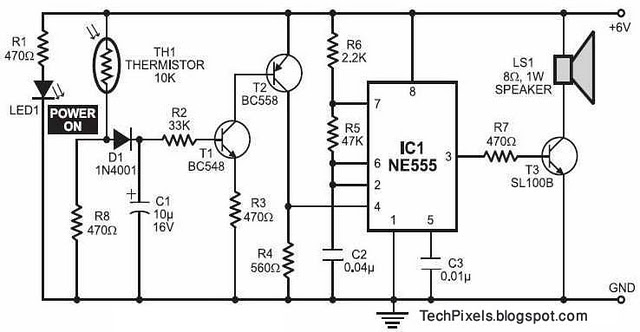
The following circuit illustrates a fire alarm circuit diagram utilizing the NE555 integrated circuit (IC). Features include functioning as a heat sensor and incorporating a 10 kilo-ohm resistor. The fire alarm circuit based on the NE555 IC is designed to...
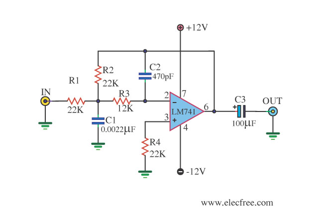
This circuit filters low frequencies below 10 kHz using the highly popular operational amplifier IC uA741. It is convenient for applications that require the conversion of analog signals to digital or vice versa. In digital sound systems, this circuit...
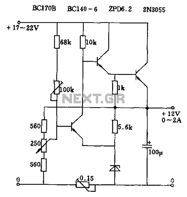
The circuit output voltage can be continuously adjusted from zero to its maximum value. The baseline is established by a constant current sourced from the auxiliary power supply circuit. The reference current of 500 microamperes can be fine-tuned to...