
Run through the display circuit equipment Chengdu

The circuit utilizes color light-emitting diodes to provide visual feedback regarding the operational status of connected electrical equipment. The red LED serves as an initial indicator of power availability, illuminating when the system is powered at 220V. The operation of the switch S plays a crucial role in determining the state of the electrical equipment. When S is closed, it allows current to flow through the TRIACs VTH1 and VTH2, which are responsible for controlling the status indicators.
TRIAC VTH1 is configured to activate when the electrical equipment is powered on and functioning correctly. Once VTH1 is activated, it effectively shorts the red LED R, extinguishing its light. At this point, the circuit transitions to the operational state, where TRIAC VTH2 is triggered to conduct, allowing the green LED G to illuminate. This change from red to green provides a clear visual indication that the electrical equipment is operating without issues.
In scenarios where the switch S is closed but the circuit is interrupted due to a blown fuse (FU) or a tripped circuit breaker, VTH1 will still receive power, thereby keeping the red LED R lit. However, the lack of conduction in VTH2 means that the green LED G will remain off. This dual-indicator system effectively communicates the operational status of the equipment, allowing for quick identification of faults in the electrical system.
The design emphasizes the importance of visual indicators in monitoring electrical equipment, enhancing user awareness and facilitating timely troubleshooting. The use of TRIACs in this configuration provides a reliable means of controlling the LED indicators based on the operational state of the equipment, ensuring that the system is both functional and user-friendly. Color light-emitting diodes with different colors of light can indicate the operating electrical equipment status, electrical equipment status indication line as shown in FIG. Power, color light-emitting diode LED red light-emitting diode R emits red light is energized, indicating 220v power supply is normal, when closing the switch S, when the electrical equipment is working properly, the TRIAC VTH1, VTH2 are turned on. VTH1 turned on, the LED red light-emitting diodes R shorting extinguished, VTH2 conduction, so that the green LED light emitting newspaper tube G emits green light, indicating the electrical equipment is working properly.
If closing the switch S, fuse or circuit breaker electrical equipment when the breaker fuse FU, although closed the s, but still indicating VTH1 supply is normal (LED glows red), green LED is not lit, electrical equipment, FU or S loop faulty.
Related Circuits
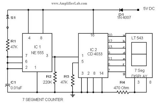
The circuit diagram of a 7-segment counter circuit has been published here. This circuit consists of the counter IC CD4033 as its central component. The 7-segment counter circuit utilizing the CD4033 integrated circuit (IC) is designed to display decimal digits...
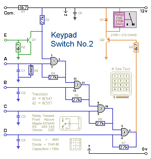
This is a simplified version of the 4-Digit Keypad Controlled Switch. The design has been modified to reduce the complexity of the circuit and the number of components required. Consequently, the code may be somewhat less secure; however, it...
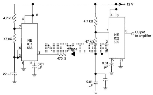
IC1 generates a pulse that modulates the 1000-Hz tone generated by IC2. This circuit can be used to generate warning or alert signals. The circuit described consists of two integrated circuits (ICs), where IC1 is responsible for generating a pulse...
The MAX1896, MAX1973, and MAX8863 are integrated circuits that provide output voltages of 5V at 225mA, 1.8V at 220mA, and 3.3V at 60mA, sourced from a USB port. USB devices typically draw power with a voltage range of 4.5V...
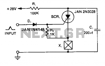
Capacitor C1 is charged to +28 V through resistor R1 and stores energy for firing the squib. A positive pulse of 1 mA applied to the gate of SCR1 will cause it to conduct, discharging C1 into the squib...
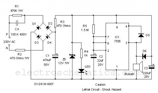
This is a simple power resumption alarm circuit that can be installed within the switch box. It emits beeping sounds when power is restored following a power outage. The power resumption alarm circuit serves as a practical solution for alerting...