
UHF Audio Video Sender Circuit
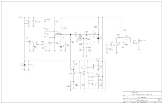
This wireless audio-video transmission circuit is designed to facilitate seamless integration of audio and visual signals for various applications, including home entertainment and security systems. At its core, the circuit employs a Colpitts oscillator, a type of oscillator known for its stability and ease of frequency adjustment, which is critical for maintaining the integrity of the transmitted signals. The components involved in the oscillator—Q3, VC1, C13, C16, and L3—work in concert to achieve the desired frequency range of 220 to 250 MHz. The tuning elements, VC1 and L3, allow for precise adjustments, enabling users to find the optimal frequency for their specific setup.
The modulation of the signal is achieved through the capacitor C13, which plays a pivotal role in determining the modulation depth. The biasing provided by R9 and C16 is crucial for ensuring that the oscillator operates within the desired parameters, and adjusting R9 influences the output level significantly, enhancing the overall performance of the circuit.
The frequency doubler stage, consisting of Q2 and L2, is important for increasing the frequency of the signal, thereby allowing for better transmission quality. The mixer stage, which combines audio and visual signals, is essential for creating a unified output that can be transmitted effectively. The use of an IF transformer, FCZ7S3R5, is vital for ensuring that the audio and video signals are synchronized, which is key for maintaining the quality of the output.
To optimize the performance of this circuit, users are encouraged to utilize a spectrum analyzer. This tool assists in accurately tuning the transmitter to the desired frequency, ensuring compatibility with the television's reception capabilities. Adjustments to the IFT can also be made to refine the output quality, particularly in cases where the image may appear unclear. Overall, this circuit represents a versatile solution for wireless audio and video transmission, catering to a variety of user needs in both entertainment and security contexts.This audio-video circuit provides you with wireless audio and visual transmission to a TV. The TV acts as a receiver, eliminating the need to buy a separate monitor. You can also hook it up to a VCR or CCD Camera, and even set up a remote CCTV security system! Q3, VC1, C13, C16 and L3 all make up a colpitts oscillator circuit that fluctuates form 220~250MHz. You can regulate the frequency to any value within this threshold by tuning VC1 or L3. C13 modulates the signal rate. When the capacitance increases, so does the modulation. R9 and C16 bias the local oscillation. If you lower R9`s frequency to 680W the oscillator`s output level will increase. Q2 and L2 act as a frequency doubler. C7, along with FCZ7S3R5 (IF transformer), the Q4 transistor, C14, C19 and R12 all make up the mixer. This mixer takes both audio and visual signals together and "mix" them into one and passes through RF Amplifier Q1 to transmit the signal to the antenna. Turning the blue component`s trimmer on VC1 varies the frequency. When we turn the trimmer, the television`s channel has to be changed accordingly. It is easier to tune the A/V Sender if you have a spectrum analyzer to help you find the correct frequencies.
If the frequency is tuned to 474 MHz then this would be the equivalent of your TV`s channel 14 UHF band. The IF transformer is used to synchronize the audio and video frequency`s level radio. If the TV`s image is too blurry then you can adjust the IFT to fine-tune the image. 🔗 External reference
Related Circuits
To measure the input impedance of an unknown circuit, first set the signal generator to a current source with a magnitude of 1 amp. A shunt resistor of 100 megohms is also required. This setup is beneficial for measuring...
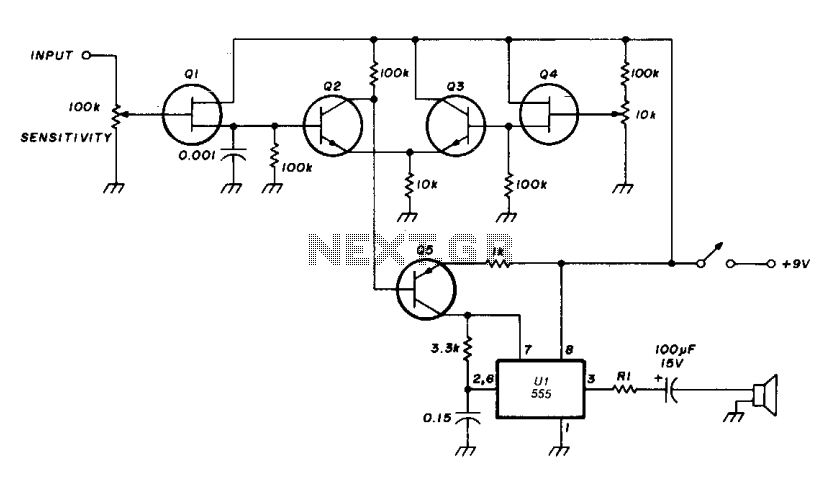
The transistor Q5 and the 1000-ohm resistor form the variable element necessary for controlling the frequency of the voltage-controlled oscillator (VCO) by limiting the charging current flowing into the 0.15 microfarad timing capacitor based on the forward bias applied...
This preamplifier is designed for low-resistance sources such as moving coil heads (MC). The circuit employs three parallel double transistors, SSM2220 or MAT03, which form a differential amplifier that minimizes noise. When connected to an OP27 amplifier, it further...
This circuit automatically activates and deactivates a motorcycle's headlight, functioning independently of both the light and ignition switches, as long as the battery is fully charged. The initial stage employs a 220-ohm resistor and ZD1 to keep transistor Q1...
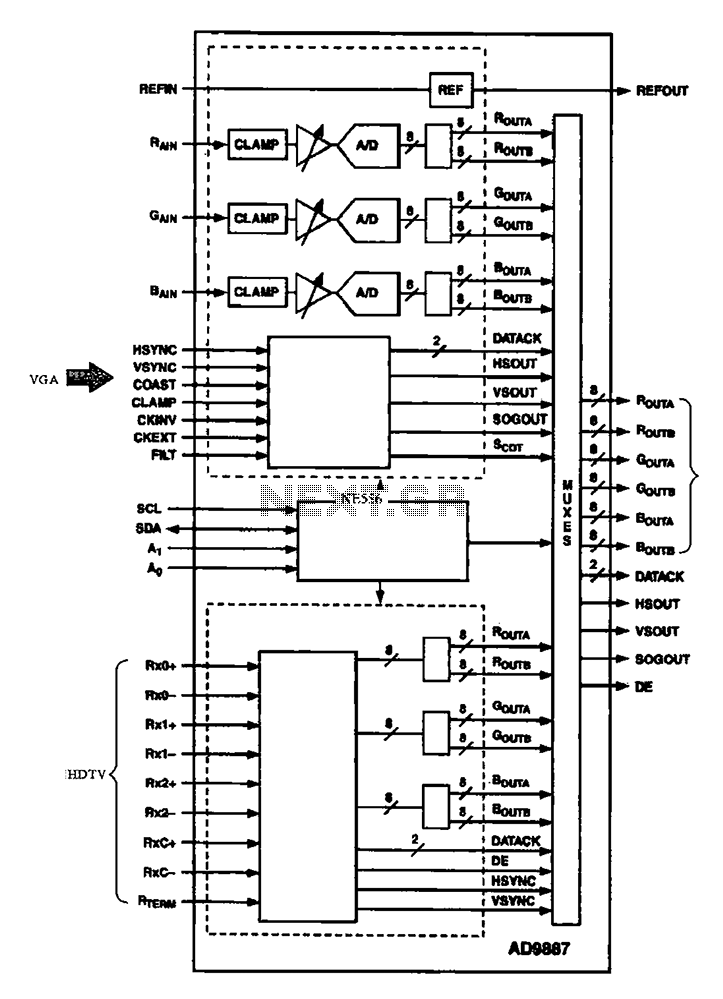
The AD9887, a commonly used video A/D converter for liquid crystal televisions, is capable of converting analog red, green, and blue (R, G, B) signals into digital signal outputs. The AD9887 is a high-performance analog-to-digital converter (ADC) specifically designed for...
Figure 1 illustrates an AND gate logic circuit with the logic expression P=A. Figure B depicts two photodiodes connected in series. When the input logic levels A=1 and B=1, the output P=1. Similarly, this configuration can be used to...