
UHF TV Antenna Booster Circuit With BF180 Transistor
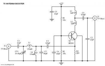
The UHF band TV antenna booster circuit is designed to enhance the signal strength received by UHF antennas, which are commonly used for digital television broadcasting. The circuit typically consists of a low-noise amplifier (LNA) that amplifies weak signals captured by the antenna. The gain of 15 dB indicates that the amplifier will increase the signal strength significantly, improving the quality of the received television signals and reducing the likelihood of pixelation or loss of picture.
The primary components of this circuit include the LNA, which is usually an integrated circuit (IC) designed for RF applications, along with passive components such as resistors, capacitors, and possibly an inductor for filtering purposes. The power supply for the circuit can be derived from a standard DC source, and it is essential to ensure that the voltage and current ratings are compatible with the LNA specifications.
The circuit layout should be designed to minimize interference and maintain signal integrity. This can be achieved by keeping the input and output traces short and using proper grounding techniques. Additionally, the use of a suitable enclosure can help shield the circuit from external electromagnetic interference.
To construct the antenna booster, the components should be assembled on a printed circuit board (PCB) or a perfboard, ensuring that all connections are secure and that the layout adheres to RF design principles. Once assembled, the circuit can be tested by connecting it to a UHF antenna and measuring the output signal strength using a signal strength meter or a compatible television receiver.
Overall, this UHF band TV antenna booster circuit offers a cost-effective solution for improving TV reception in areas with weak signal coverage, making it a valuable addition to any home entertainment system.This is a very simple circuit of UHF band TV antenna booster with 15dB gain power. This low cost antenna booster is simple and easy to build. This .. 🔗 External reference
Related Circuits
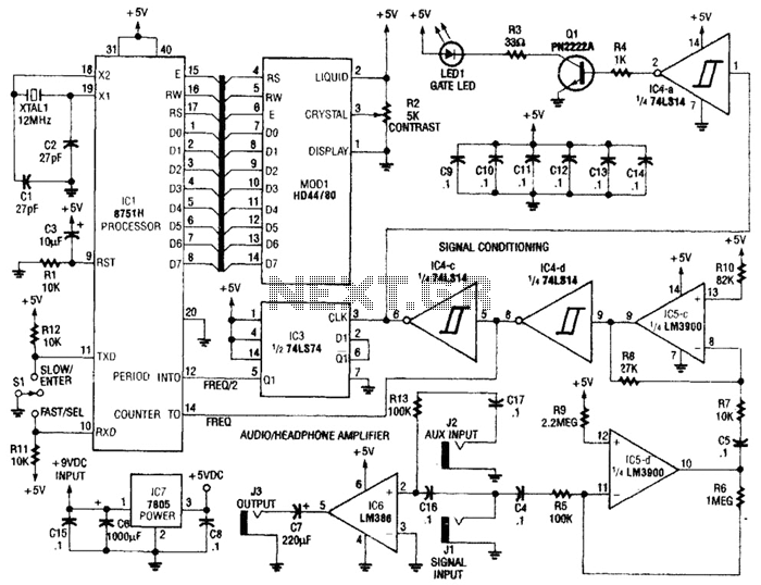
Perfect Pitch, which is based on the 8751 microprocessor, is an affordable and straightforward instrument tuner and frequency counter that features a built-in headphone amplifier and a visual metronome. Perfect Pitch converts the audio signal from an instrument into...
How the processor produces 3 as the output. This question may be challenging to answer in simple terms. If so, a link to a book would be helpful. The process by which a processor generates the output of the number...
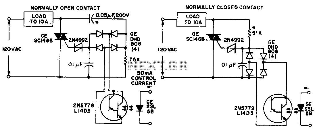
Both circuits utilize the GE SC146B, a 200 V, 10 A Triac for load current contacts. These triacs are activated by standard SBS (2N4992) trigger circuits, which are managed by a photo-Darlington configuration, functioning through the DA806 bridge as...
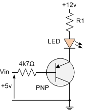
The PNP transistor is the exact opposite of the NPN transistor discussed in the previous tutorial. In this type of transistor construction, the two diodes are reversed compared to the NPN type, resulting in a Positive-Negative-Positive configuration, with the...
This amplifier is designed to be self-contained within a compact loudspeaker enclosure. It can be powered by devices such as Walkmans, Mini Discs, iPods, CD players, computers, and other devices equipped with line or headphone outputs. Typically, two units...
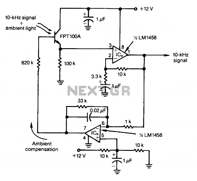
The feedback control of the phototransistor in this optical detector helps negate the effects of varying ambient light sources. The output of a modulated visible-light LED is detected, amplified, buffered, and fed through a low-pass filter. Ambient light signals...
Warning: include(partials/cookie-banner.php): Failed to open stream: Permission denied in /var/www/html/nextgr/view-circuit.php on line 713
Warning: include(): Failed opening 'partials/cookie-banner.php' for inclusion (include_path='.:/usr/share/php') in /var/www/html/nextgr/view-circuit.php on line 713