
microprocessor Map processor to circuit diagram

The process by which a processor generates the output of the number 3 involves several key operations, including data input, processing, and output generation. In a typical scenario, the processor receives input data, which can be in the form of binary numbers representing various values. The processor utilizes its arithmetic logic unit (ALU) to perform calculations or logical operations on this data.
For the processor to output the value of 3, it must first interpret the input data correctly. This can involve reading binary representations from memory, where the number 3 is stored as a binary value (i.e., 0011 in 4-bit binary). The processor executes instructions from its instruction set architecture (ISA) to manipulate this data. For example, if the input includes the numbers 1 and 2, the processor can execute an addition operation to calculate their sum, resulting in 3.
The processor's control unit orchestrates these operations by fetching instructions, decoding them, and executing them in the correct sequence. It ensures that the ALU receives the appropriate inputs and performs the necessary calculations. Once the result is computed, it is sent to the output interface, which can display the value on a screen, send it to a peripheral device, or store it in memory for future use.
In summary, the generation of the output value 3 by a processor is a multi-step process that involves input interpretation, arithmetic operations, and output delivery, all governed by the processor's architecture and instruction set. Understanding this process may require further reading on digital logic design and computer architecture for a deeper insight into how processors function at a fundamental level.How the processor produces `3` as the output. I realise that this question may be difficult to answer in simple terms. If it is, then a link would help, perhaps to a book. 🔗 External reference
Related Circuits
In an audio amplifier, the quality of sound depends on several factors, including the quality of active and passive components, circuit configuration, and layout. The selection of components is influenced by the constructor's budget. Discrete active components like transistors...
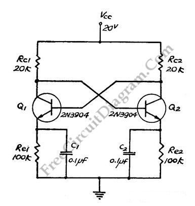
This flip-flop circuit functions as a free-running astable multivibrator, where the bases and collectors of both emitter-biased transistors are directly coupled. The switching action is facilitated by a capacitor in each emitter circuit, resulting in the generation of triangle...
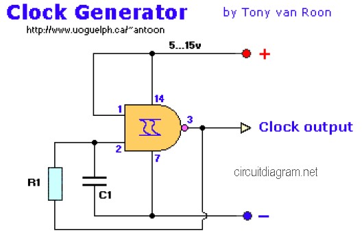
The following diagram is the clock generator circuit diagram built using NAND gate logic integrated circuits (ICs). The circuit can utilize either the IC 7400, which is a TTL type, or the IC 4011, which is a CMOS type....
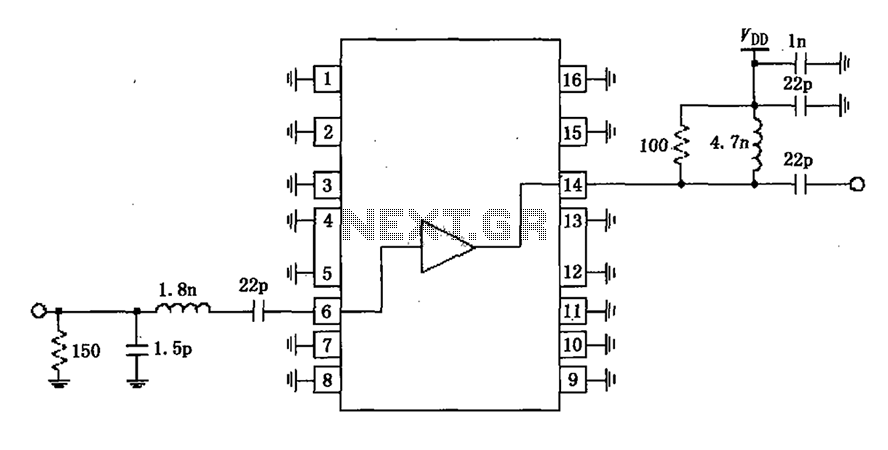
A narrowband linear amplifier circuit configured with the RF2320 operates within a frequency range of 1930 to 1990 MHz. The radio frequency (RF) signal is input from a distance of 6 feet and is amplified by an internal amplifier...
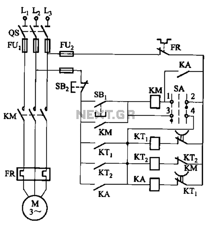
The circuit illustrated in Figure 3-78 utilizes two relays for automatic control, featuring a more complex line structure. This configuration allows for intermittent motor operation. Additionally, it can operate continuously when switch SA is positioned to the right. The circuit...
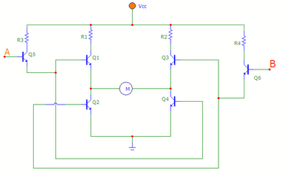
The transistors Q1, Q2, Q3, and Q4 form a bridge circuit. These are typically power transistors designed to handle high current. Transistors Q5 and Q6 drive the bridge. When input A is set high and input B is set...