
Very Low Frequency Multivibrator Circuit
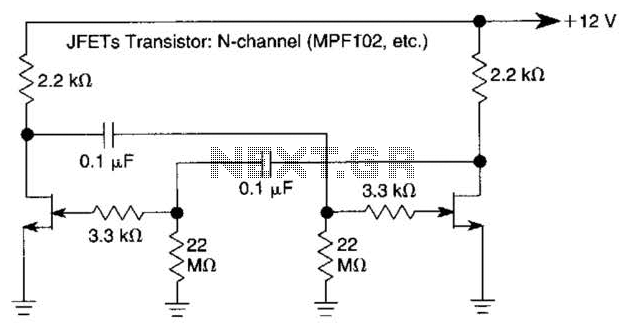
In the context of electronic circuit design, a multivibrator is a circuit that generates a continuous output signal, which can be either square or pulse waveform. In this specific design, the implementation of Junction Field-Effect Transistors (JFETs) plays a crucial role in achieving the desired operational characteristics. JFETs are known for their high input impedance, which minimizes loading effects on preceding stages of the circuit, thereby maintaining signal integrity.
The design operates at a very low frequency of 0.15 Hz, which necessitates long time constants. This is achieved through the careful selection of passive components, such as resistors and capacitors, which determine the charging and discharging rates in the circuit. The high resistance values used in conjunction with larger capacitance values contribute to the extended time constants, allowing for the low frequency operation.
In practical terms, this multivibrator configuration can be used in applications where slow oscillation is required, such as in timers, oscillators for low-frequency signals, and other timing applications. The stability and reliability of the output signal at such low frequencies can be significantly enhanced by the use of JFETs, making this design advantageous for specific electronic applications. Proper simulation and testing should be conducted to ensure that the circuit meets the required specifications and performance criteria. The use of JFETs permits, high resistance and long time constants in this very low frequency multivibrator. The values shown are for 0.15 Hz operation. 🔗 External reference
Related Circuits
This circuit generates sine wave oscillations, but it can also be modified to produce triangle or square wave functions. The frequency is adjustable by varying the current. By disconnecting the 20k resistor (RIN) from the reference (REF) pin (pin...
A PLL oscillator, or phase-locked loop oscillator, is a control method that compares a controlled system or plant to a reference signal. A phase-locked loop (PLL) oscillator is a sophisticated electronic circuit designed to synchronize an output signal's phase and...
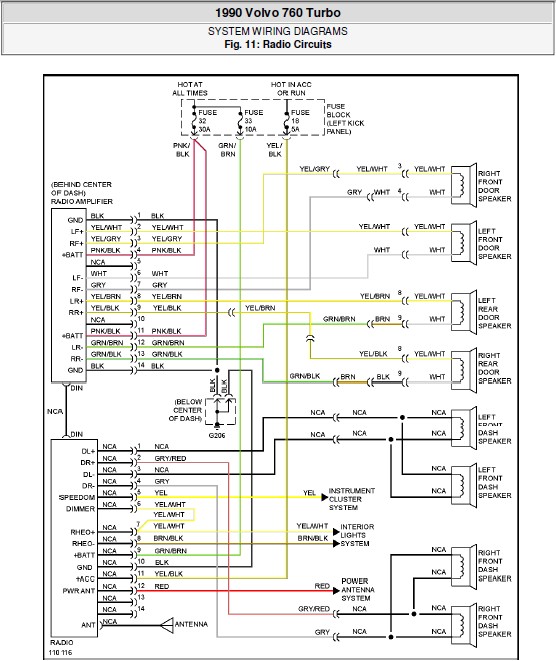
The following document contains the system wiring diagram of the radio circuit for the Volvo 760 Turbo 1990. Please note that this is a system wiring diagram, not a schematic diagram. Download the radio circuit system wiring for the...
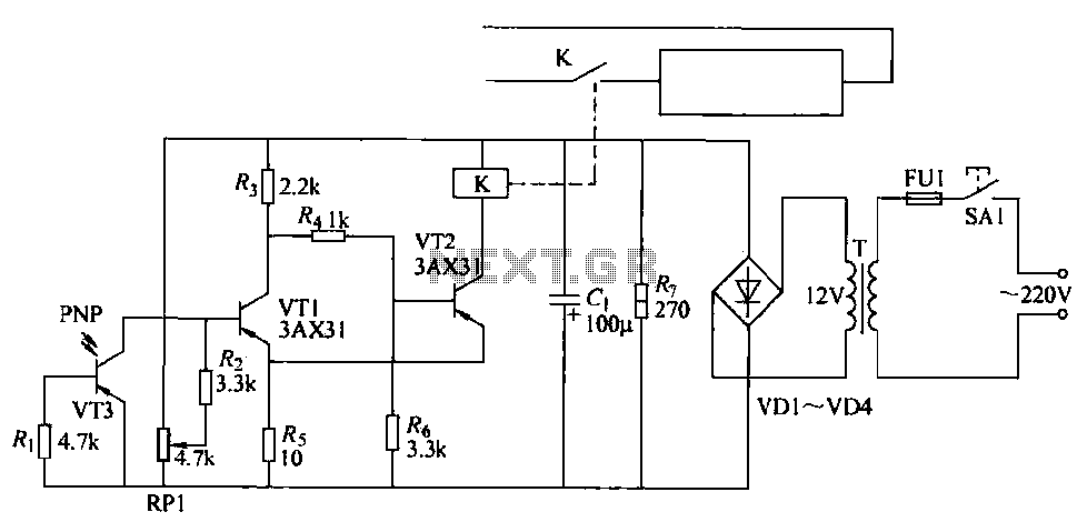
The cutter is safeguarded by a printed circuit phototransistor designed to prevent accidental activation of the cutter switch during manual feeding. In the event of manual feeding, the automatic paper cutter can be controlled to shut down. A relay...
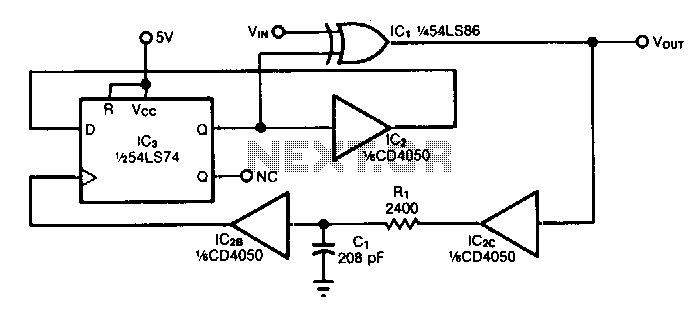
The circuit doubles the frequency of a digital signal by operating on both signal edges. Each transition causes the exclusive-OR gate IC1 to produce a pulse, which clocks flip-flop IC3 after propagating through buffers IC2C and IC2B. If capacitor...
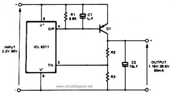
The IC8211 serves as a voltage reference and regulator amplifier, with Q1 likely functioning as the series pass transistor. R1 determines the output current of the IC8211, while C1 and C2 contribute to loop stability and help suppress the...
Warning: include(partials/cookie-banner.php): Failed to open stream: Permission denied in /var/www/html/nextgr/view-circuit.php on line 713
Warning: include(): Failed opening 'partials/cookie-banner.php' for inclusion (include_path='.:/usr/share/php') in /var/www/html/nextgr/view-circuit.php on line 713