
BCD to Seven Segment Decoder IC description

The integrated circuit (IC) in question is designed to control a 7-segment LED display, which is a common component in digital readouts. The outputs of the IC directly correlate to the individual segments of the display, enabling the representation of numerical values from 0 to 9 and potentially letters depending on the configuration.
The functionality of the BI/RBO as wire-OR logic is crucial for managing the display's output. The blanking input (BI) allows for the display to be turned off or blanked out, which is essential in scenarios where the display should not show any output, such as during initialization or in error states. The ripple-blanking output (RBO) serves to cascade blanking signals to other displays or segments, ensuring that all components remain synchronized in their output state.
In operation, when the blanking input is held high or open, the IC can produce outputs corresponding to all decimal values from 0 to 15. However, if the blanking input is forced low, the IC overrides any other input conditions, ensuring that all segments are turned off. This provides a fail-safe mechanism to prevent unintended display states.
The ripple-blanking input (RBI) further enhances the control over the display. When RBI is low, combined with specific conditions on the lamp test input and the states of A, B, C, and D, the IC will again drive all segment outputs low. This can be useful for diagnostics or testing, allowing the user to verify that the display segments are functioning correctly.
Lastly, the interaction between the lamp test input and the segment outputs is noteworthy. When the lamp test input is activated (held low) while the blanking input is high, the segments will illuminate, allowing for a visual check of the display functionality. This feature is particularly useful in troubleshooting and maintenance scenarios, ensuring that all segments are operational before deploying the display in a final application.
Overall, the described integrated circuit provides a robust and flexible architecture for controlling a 7-segment LED display, with various inputs and outputs designed to facilitate both normal operation and diagnostic functions.Note how the output letters of the integrated circuit [Output A] match with the Diode letters in the 7-Segment LED above. Each IC output corresponds to a particular input [diode] of the seven segment display. 1. BI/RBO is wire-OR logic serving as blanking input (BI) and/or ripple-blanking output (RBO). The blanking input must be open or held at ahigh logic level when output functions 0 through 15 are desired, and ripple-blanking input (RBI) must be open or at a high logic level during the decimal 0 output. X = input may be high or low. 2. When a low logic level is applied to the blanking input (forced condition) all segment outputs go to a low logic level regardless of the state of any other input condition.
3. When ripple-blanking input (RBI) is at a low logic level, lamp test input is at high logic level and A = B = C = D = low logic level, all segment outputs go to a low logic level and the ripple-blanking output goes to a low logic level (response condition). 4. When blanking input/ripple-blanking output is open or held at a high logic level, and a low logic level is applied to lamp test input, all segment outputs go to a high logic level.
🔗 External reference
Related Circuits
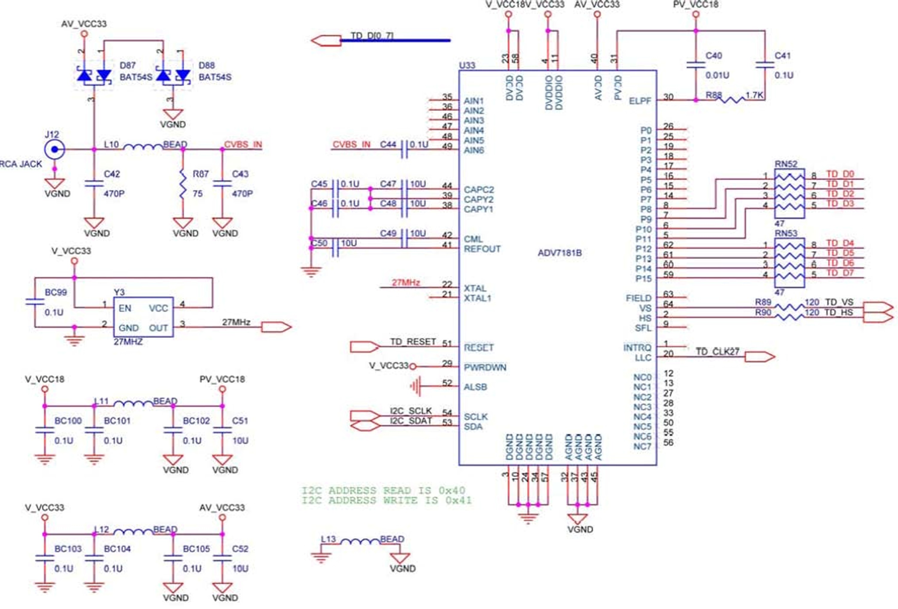
The DE2 board features an Analog Devices ADV7181 TV decoder chip. The ADV7181 is an integrated video decoder that automatically detects and converts standard analog baseband television signals (NTSC, PAL, and SECAM) into 4:2:2 component video data, which is...
7-Segment Common LED UV Exposure Box Circuit Diagram. Features: Utilizes Stan Ocker's circuit design, employing a PIC16F84 microcontroller to count and display the time. The 7-Segment Common LED UV Exposure Box Circuit is designed for applications requiring precise timing and...
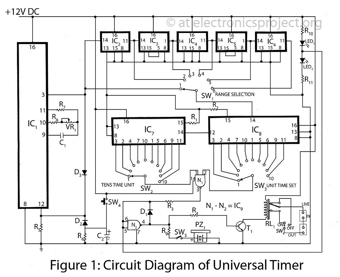
The Universal Timer is a highly versatile timer project that accommodates a wide range of time periods, from 1/10th of a second to 100 hours. This circuit diagram includes a comprehensive description of various timer circuits associated with the...
This is an image Schematic. No Description available. The provided input indicates that there is a schematic image, but no additional descriptive information is available regarding its components, functionality, or application. In the context of electronic schematics, such images...
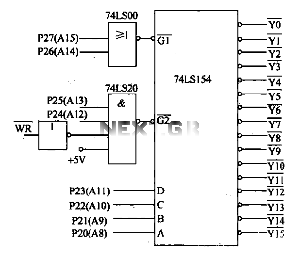
Decoding circuit: To ensure proper functionality of various interfaces, the system must assign IP addresses to all ports. Based on the number of system interfaces, it utilizes the 74LS154 decoder, which can translate up to 16 addresses. The interface...
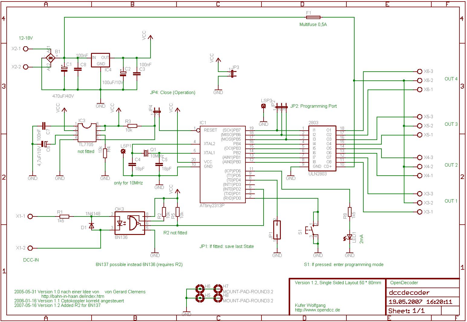
This software was developed specifically for the hardware in question. Consequently, the pin allocation of the Atmel ATtiny2313 in this circuit corresponds to the original design, allowing the software to operate on both hardware platforms. An important note is...