
ultra capacitor technology powers electronic circuits
Ultracapacitors are particularly suited for applications requiring rapid charge and discharge cycles, such as in regenerative braking systems in electric vehicles or as backup power sources in renewable energy systems. Their ability to deliver high power instantaneously makes them ideal for applications where quick bursts of energy are necessary, such as in power tools or consumer electronics that demand high peak currents. The development of ultracapacitors continues to focus on enhancing their energy density while maintaining their advantageous properties of high power density and long cycle life. The integration of advanced materials and innovative manufacturing techniques is crucial for overcoming current limitations and expanding their applicability across various sectors, including automotive, aerospace, and consumer electronics. The exploration of hybrid systems that combine ultracapacitors with traditional batteries may also yield significant improvements in overall system performance, allowing for optimized energy management and enhanced device longevity.As the market strives for lighter, more compact wireless and portable devices with more ingenious features crammed into an ever-tighter space, a related quest ensues for the next power supply innovation ” a powerful, compact, long-lasting, economical and safe battery. Although progressing toward this end, current battery technology often comprom ises the desired space and weight specifications without properly satisfying peak power requirements. Ultracapacitors, also known as supercapacitors, offer an alternative source that promises to circumvent the battery scramble and extract greater efficiency from existing power sources.
Because of high price and manufacturability issues, this electric double layer capacitor (EDLC), also known as a pseudo capacitor, isn`t popular among engineers. However, it offers boundless growth potential because it responds to key market and societal needs: It`s environmentally friendly, helps conserve energy, and enhances the performance and portability of consumer devices.
Ultracapacitors also are free from characteristic battery problems, such as limited cycle life, cold intolerance and critical charging rates. Ultracapacitors are being developed as an alternative to pulse batteries. To be an attractive alternative, ultracapacitors must have at least one order of magnitude higher power and a much longer shelf and cycle life than batteries.
Ultracapacitors have much lower energy density than batteries, and their low-energy density is, in most cases, the factor that determines the feasibility of their use in a particular high-power application. Available for decades, a conventional electrolytic capacitor is an energy-storage device that can be compared to a container that gradually fills with electrical energy and then delivers it when needed in a sudden burst.
Offered just recently, an ultracapacitor is a high-energy version of a conventional capacitor, holding hundreds of times more energy per unit volume or mass than the latter by using state-of-the-art materials and high-tech microscopic manufacturing processes. When fully charged, these robust devices deliver instant power in an affordable, compact package. Long considered an enigma because of price, the advent of inexpensive, compact ultracapacitors, characterized by an exceptionally high surface area, excellent conductivity, and superior chemical and physical stability, herald a new era of practical usage.
The equivalent circuit used for conventional capacitors can also be applied to ultracapacitors. The circuit schematic in Fig. 2 represents the first-order model for an ultracapacitor. It`s comprised of four ideal circuit elements: a capacitance C, a series resistor Rs, a parallel resistor Rp, and a series inductor L. Rs is called the equivalent series resistance (ESR) and contributes to energy loss during capacitor charging and discharging.
Rp simulates energy loss due to capacitor self-discharge, and is often referred to as the leakage current resistance. Inductor L results primarily from the physical construction of the capacitor and is usually small. However, in many applications, it can`t be neglected ” particularly those operating at high frequencies or subjected to hard switching.
Resistor Rp is always much higher than Rs in practical capacitors. Thus, it often can be neglected, particularly in high-power applications. In that case, the impedance of the Fig. 2 circuit model is: Z = R + i (2pfL-1/2pfC), where L is the inductance in [Henrys]. The impedance is purely resistive when 2pfL-1/2pfC = 0, or f = 1/2 p(LC) ½. This particular frequency is referred to as the resonance frequency of the capacitor. Thus, the impedance of circuit is simply the resistance at self-resonance. However, ultracapacitors exhibit non-ideal behavior, which result primarily from the porous material used to form the electrodes that cause the resistance and capacitance to be distributed such that the 🔗 External reference
Related Circuits
A fast electronic fuse designed to operate on 230V AC with an adjustable trip current. When the current through the load exceeds a level determined by the user, the fuse will trip to protect the circuit. The electronic fuse functions...
Most individuals are unaware that there are typically over a dozen battery backup systems present in their homes. The average American has around 18 battery-backed devices in their household. These battery backup systems protect crucial, expensive, or portable electronics...
A novel method of hydrogen generation through water electrolysis utilizing an ultra-short-pulse power supply is presented. The process of hydrogen generation via water electrolysis involves the splitting of water molecules (H2O) into hydrogen (H2) and oxygen (O2) gases using electrical...
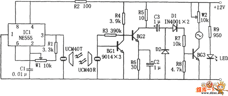
The image depicts an ultrasonic liquid level indicator circuit. This circuit consists of an ultrasonic transmitter circuit and a receiver circuit. The ultrasonic transmitter circuit includes a 555 timer, resistor R1, variable resistor W1, capacitor C1, and the ultrasonic...
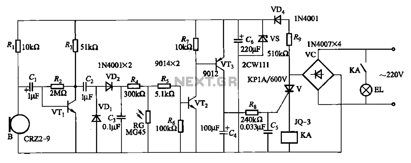
A resistor R8, capacitors Cd, and a thyristor V AC switch form a delay circuit. The lamp's lighting delay time is determined by the resistor Rs and capacitor C4, with a delay of approximately 40 seconds as indicated in...
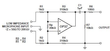
This microphone preamp schematic is an electronic circuit project utilizing the OP37 operational amplifier from Analog Devices. It functions as a fixed-gain transformerless microphone preamp, amplifying differential signals from low-impedance microphones by 50 dB, with an input impedance of...
Warning: include(partials/cookie-banner.php): Failed to open stream: Permission denied in /var/www/html/nextgr/view-circuit.php on line 713
Warning: include(): Failed opening 'partials/cookie-banner.php' for inclusion (include_path='.:/usr/share/php') in /var/www/html/nextgr/view-circuit.php on line 713