
Ultrasonic Liquid Level Indicator Circuit Composed Of NE555
The ultrasonic liquid level indicator operates by emitting high-frequency sound waves from the ultrasonic transmitter head (UCM40T). The 555 timer functions as an oscillator, generating a pulse signal that drives the transmitter. Resistor R1 and variable resistor W1 are used to adjust the frequency and duty cycle of the output signal, while capacitor C1 helps to stabilize the oscillation.
When the sound waves emitted by the transmitter encounter the liquid surface, they are reflected back towards the receiver head (UCM40R). The receiver detects these reflected sound waves and converts them into an electrical signal. The cascade amplifier (BG1) amplifies this signal for further processing. The time taken for the sound waves to return is proportional to the distance between the transmitter and the liquid surface, allowing for accurate measurement of the liquid level.
This circuit can be utilized in various applications, including water tanks, industrial processes, and other areas where liquid level monitoring is essential. The design allows for non-contact measurement, minimizing maintenance and ensuring reliability in diverse environments. Proper calibration of the components is critical to achieve optimal performance and accuracy in liquid level detection.The picture shows the ultrasonic liquid level indicator circuit. This circuit is made up of ultrasonic transmitter circuit and receiver circuit.The ultrasonic transmitter circuit is made up of 555, R1, W1, C1 and ultrasonic transmitter head UCM40T. The ultrasonic receiver circuit is made up of the corresponding receiving head UCM40R, cascade amplifier BG1..
🔗 External reference
Related Circuits
PC parallel port can be very useful I/O channel for connecting your own circuits to PC. The PC's parallel port can be used to perform some very amusing hardware interfacing experiments. The port is very easy to use when...
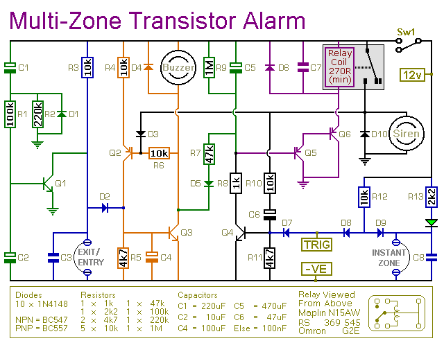
This transistor-based alarm features automatic exit and entry delays, along with a timed bell cut-off and system reset. In addition to the exit/entry zone, the basic alarm board includes one instant zone, which is sufficient for many applications. However,...

The Saver V5.0 operates a simple clock emulation program that controls a night light to turn on and off at preset times, specifically from 19:00 to 22:00 daily. This design is characterized by its low cost, easy installation, lack...
You may be familiar with this effect. You switch audio equipment such as an amplifier to a different input and there is a loud click or "thump" in the speaker system. Not all equipment is affected. Some high-end audio...
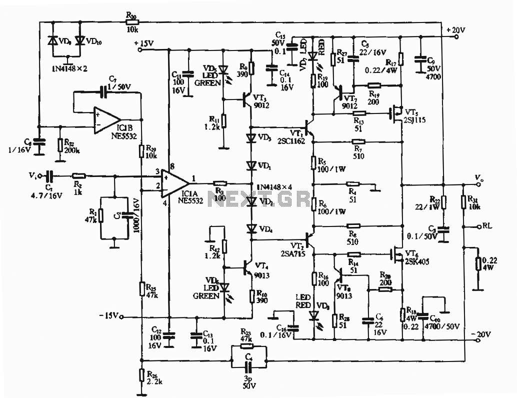
The circuit utilizes an FET amplifier configuration for output, incorporating an NE5532 operational amplifier powered by a 15V supply. The output stage features a FET that amplifies the voltage after passing through several stages. The bias circuit for the...
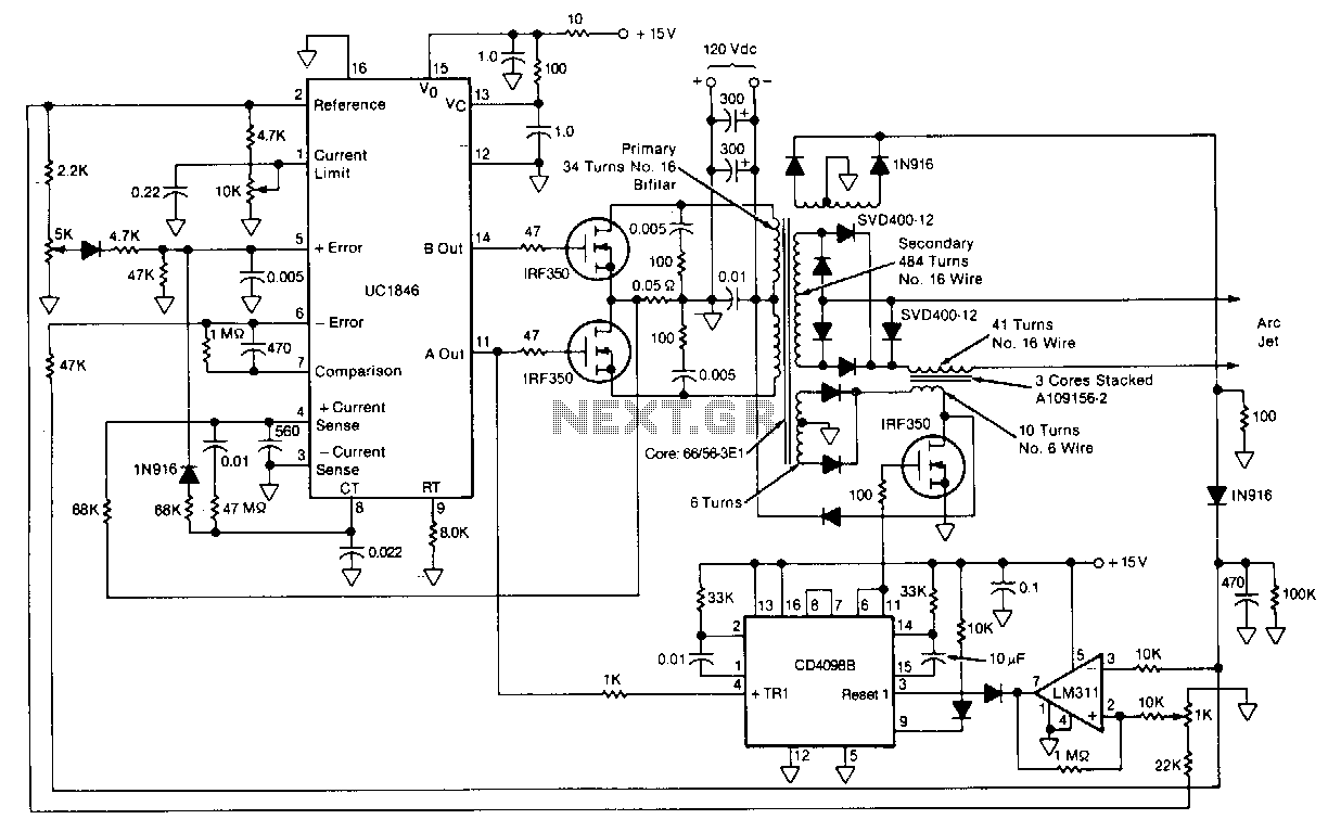
This circuit for starting arc jets and controlling them in steady operation is capable of high power efficiency and can be constructed in a lightweight form. The design comprises a pulse-width-modulated power converter, which is configured in a closed...