
Quiz Master Circuit
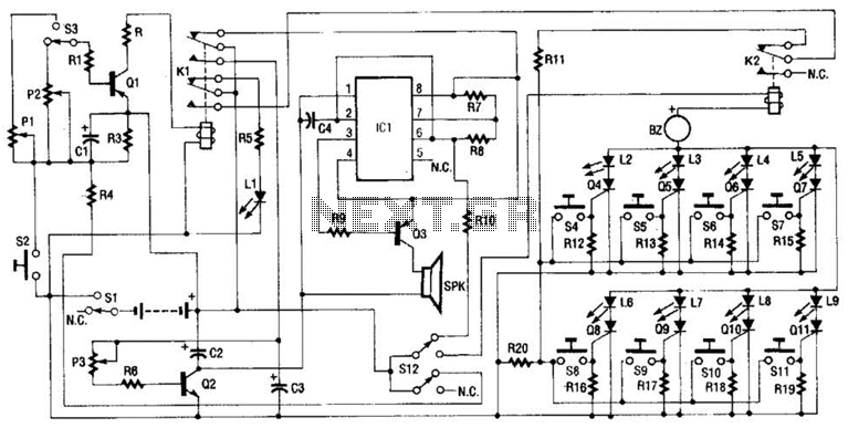
As soon as a contestant presses their switch button (S4 through S11), a positive bias is applied to the respective SCR gate. This bias latches the contestant's SCR on, which in turn lights up the appropriate LED on the master control board. Simultaneously, the activation of the SCR triggers the answer buzzer (BZ) and locks out all other contestants. The lockout occurs because relay K2 contacts operate to remove the availability of a bias voltage to the gates of the other SCRs. Additional circuitry includes a timer circuit and a timeout tone-generating circuit. The timer circuit consists of transistor Q1, capacitor C1, resistors R1 through R3, and trimmer resistors P1 and P2. Depending on the adjustment of the trimmer resistors and selection switch S3, a specific time period can be set. The timeout tone-generating circuit is composed of IC1, transistors Q2 and Q3, along with the associated resistors and capacitors. The duration of the tone can be adjusted using P3. Relay K1, which is activated by the timer circuit, serves to reset the entire unit for the next question.
The circuit is designed for a competitive answering system where multiple players can participate simultaneously. Each player's answer button is connected to a Solid State Relay (SCR), allowing for quick response times and efficient locking out of other players once a button is pressed. The master control board provides visual feedback through the LED indicators, ensuring clarity in identifying the first contestant to answer. The timeout feature is critical in maintaining the pace of the game, requiring players to respond within a set timeframe, thus adding an element of urgency and excitement.
The timer circuit utilizes a combination of transistors and capacitors to create a delay mechanism that determines how long a player has to respond after buzzing in. The adjustable trimmer resistors allow for customization of the timeout period to suit different game formats or player preferences. The tone-generating circuit is responsible for producing an audible signal when the time runs out, alerting players that they have exceeded their allotted response time.
Overall, this electronic schematic is a robust solution for interactive quiz games, ensuring fair play and enhancing the competitive experience through its well-designed locking mechanism and visual/audio feedback systems. Up to eight players each have their own answer button to press, corresponding to the four Red Team and four Green Team LEDs on the master control board. As soon as the first contestant who thinks that he knows the answer presses the button, a loud tone sounds, all other contestants are locked out, and the contestant`s indicator LED lights on the control board so that it`s obvious who buzzed in first.
The control board also features two selectable time out periodseach adjustable from 3 to 15 seconds, setting specified time intervals in which the player must answer before the time`s up! tone sounds. Eight SCRs form the heart of the circuit. The anode of each SCR has a positive (+) bias on it by way of an LED and a negative (-) bias on cach cathode.
As soon as a contestant depresses his or her switch button (S4 through Sll), a positive bias is applied to the respective SCR gate. That bias latches the contestant`s SCR on, which in turn lights up the appropriate LED on the master control board.
At the same time, the activity of the SCR latching on turns on the answer buzzer (BZ) and locks out all other contestants. The lockout occurs because relay K2 contacts operate to remove the availability of a bias voltage to the gate of the other SCRs.
The other circuitry consists of a timer circuit and a time`s-up tone-generating circuit. The timer circuit consists of transistor Ql, capacitor CI, resistors Rl through R3, and trimmer resistors PI and P2, Depending on the adjustment of the trimmer resistors and selection switch S3, a specific time period can be set. The lime`s-up tone-generating circuit is made up of IC1, transistors Q2 and Q3, and the associated resistors and capacitors.
The on time of the tone can be set by P3. Relay Kl, which is operated by the timer circuit, serves to reset the entire unit for the next question. 🔗 External reference
Related Circuits
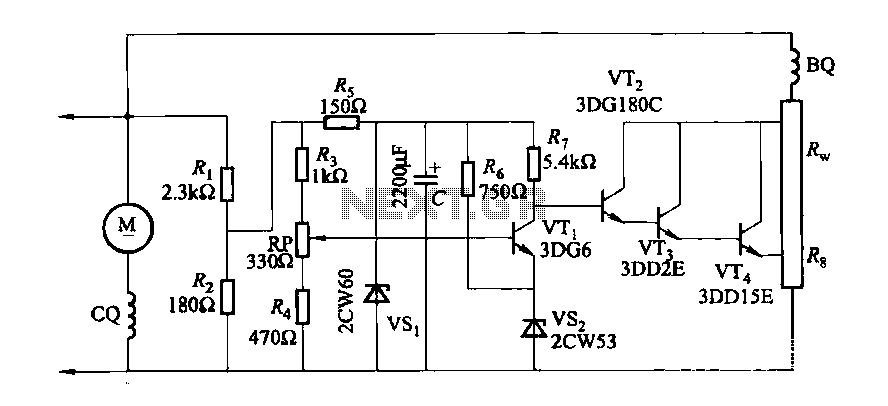
The DC generator automatic voltage regulator circuit is illustrated in Figure 7-53. This circuit is designed for a 40kW, 230V DC shunt complex machine, with a voltage change rate of up to 2.5 percent. In Figure 7-53, BQ represents...
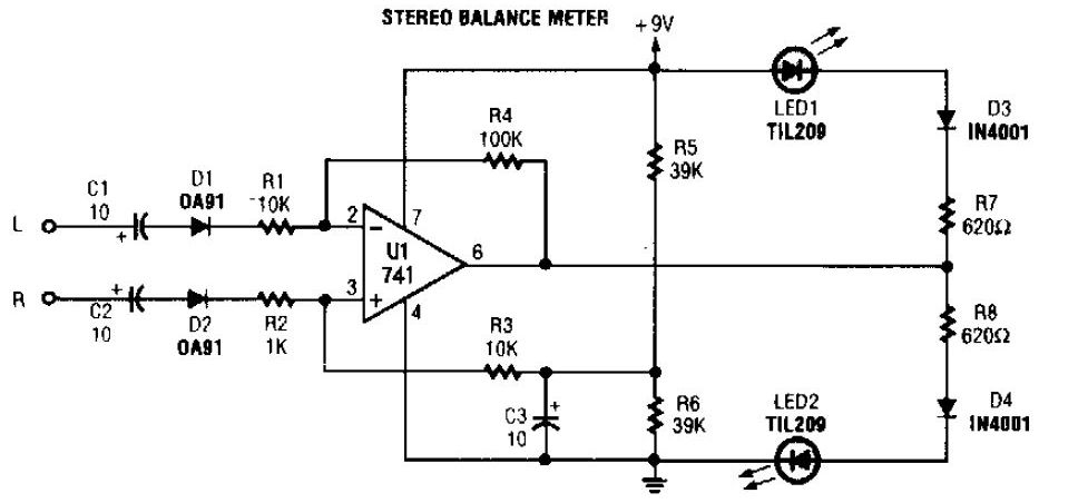
The simplest stereo balance meter circuit schematic available on the internet. When the left and right signals are equal, no output is present from U1 and pin. This stereo balance meter circuit is designed to visually indicate the balance between...
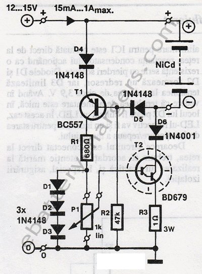
This 24V to 36V linear battery charger is long overdue. While this is an old circuit technique, it is optimized for charging higher voltage lead-acid batteries. The 24V to 36V linear battery charger is designed to provide a stable charging...
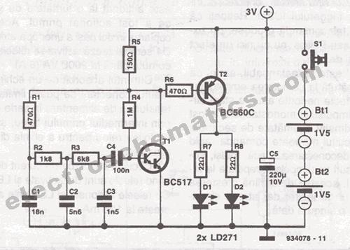
This infrared transmitter is designed for use with an infrared receiver. It operates using either two 1.5V batteries or a 3V lithium battery, allowing for a compact infrared communication system. The infrared transmitter circuit typically consists of an infrared LED,...
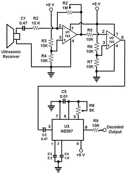
The ultrasonic receiver utilized in this circuit is specifically designed to vibrate optimally at a frequency of approximately 40 kHz. Consequently, the transmitter associated with this receiver must also emit waves at 40 kHz. When these waves interact with...
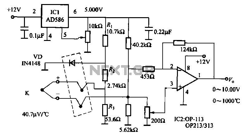
The circuit includes a K-type thermocouple cold junction compensation circuit, a precision 5.000V reference voltage source, and an OP113 operational amplifier. It is capable of measuring temperatures ranging from 0°C to 100°C with a resolution of 0.02°C. The OP113...