
Ultra Low Drop Linear Voltage Regulator

This MOSFET-based linear voltage regulator circuit is designed for efficient voltage regulation with minimal voltage drop and high output current capability. The use of an IRF540 N-channel MOSFET allows for robust performance, handling up to 3A output current when adequately heatsinked. The transformer provides the necessary AC voltage, which is rectified and smoothed by the voltage doubler circuit, ensuring that the gate drive voltage for the MOSFET is sufficiently elevated for optimal operation.
The TL431 serves as a precision voltage reference and error amplifier, ensuring that the output voltage remains stable despite variations in load conditions. The feedback loop, facilitated by the voltage doubler and resistor R3, allows for real-time adjustments to the gate voltage, maintaining the desired output voltage of 12V. The inclusion of a trimpot (VR1) allows for precise calibration of the output voltage, accommodating any variations in component values or desired output specifications.
The compensation network composed of resistor R5 and capacitor C6 ensures stability in the feedback loop, preventing oscillations that could compromise the performance of the regulator. Furthermore, the crowbar protection mechanism is crucial for safeguarding the circuit against short-circuit conditions. By using the MOC3021 Triac optocoupler, the circuit can effectively disconnect the gate drive from the MOSFET in the event of an overload, preventing damage to the components and ensuring safe operation.
Overall, this circuit exemplifies a well-designed linear voltage regulator that combines efficiency, stability, and protection features, making it suitable for a variety of applications requiring reliable voltage regulation.This circuit is a Mosfet-based linear voltage regulator with a voltage drop of as low as 60mV at 1A. The circuit uses a 15V-0-15V transformer and employs an IRF540 N-channel Mosfet (Q1) to deliver the regulated 12V output. The gate drive voltage required for the Mosfet is generated using a voltage doubler circuit consisting of diodes D1 & D2 and c
apacitors C1 & C2. To turn the Mosfet fully on, the gate terminal should be around 10V above the source terminal which is connected to the DC output. The voltage doubler feeds this voltage to the gate via resistor R3. IC2, a TL431 adjustable shunt regulator, is used as the error amplifier. It dynamically adjusts the gate voltage to maintain the regulation at the output. With an adequate heatsink for the Mosfet, the circuit can provide up to 3A output at slightly elevated minimum voltage drop.
Trimpot VR1 is used for fine adjustment of the output voltage. The RC network consisting of R5 and C6 provides error-amplifier compensation. The circuit is provided with short-circuit crowbar protection to guard against an accidental short at the output. This crowbar protection works as follows: under normal working conditions, the voltage across capacitor C5 will be 6.
3V and diode D5 will be reverse-biased by the output voltage of 12V. However, during output short-circuit conditions, the output will momentarily drop, causing D5 to conduct. This triggers the MOC3021 Triac optocoupler (IC1) which in turn pulls the gate voltage to ground. This limits the output current. The circuit will remain latched in this state and the input voltage has to be switched off to reset the circuit.
🔗 External reference
Related Circuits
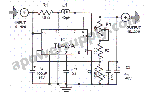
This voltage converter is constructed using the TL497A integrated circuit and is designed to convert an input voltage range of 5 to 12 volts into a higher output voltage range of 15 to 30 volts. This functionality is particularly...
As Ron suggests, controlling the output voltage from a regulator can be made variable in three ways. Using a fixed reference zener diode to increase the output by the value of the zener. A variable resistor for variable output,...
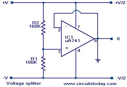
Voltage splitter using op-amp uA741 IC, circuit diagram, working, description. The voltage splitter circuit utilizing the uA741 operational amplifier (op-amp) is designed to provide a stable output voltage that is a fraction of the input voltage. The uA741 is a...
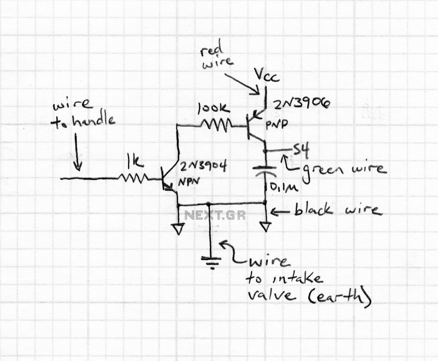
This is the fifth iteration of a robot named Cruddy version 2. It functions as a line-following robot and features an improved circuit design, originally conceived by the designer. Notably, this project does not utilize a microcontroller; instead, it...

This project presents a practical application in security and alarm systems for homes, shops, and vehicles. It consists of a set of ultrasonic receivers and transmitters operating at the same frequency. The design features an ultrasonic radar circuit. The...
Introduction to the Reflow Process and PID Controller Circuit Documentation. This document discusses the benefits of using Surface Mount Devices (SMD) in circuit design, highlighting advantages such as reduced size and cost compared to traditional through-hole components. The reflow soldering...