
Variable Voltage Regulation
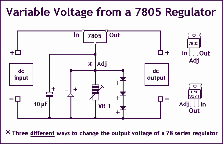
Controlling the output voltage of a voltage regulator can be achieved through several methods, each with its own advantages and limitations. The first method involves the use of a fixed reference zener diode. In this configuration, the zener diode is connected in parallel with the output of the regulator. The output voltage can be increased by the zener voltage, effectively allowing for a higher regulated output. It is essential to select a zener diode with a breakdown voltage that meets the desired output requirements.
The second method utilizes a variable resistor, or potentiometer, to adjust the output voltage. This approach allows for fine-tuning of the output voltage within a specified range. However, it is crucial to note that the output voltage cannot be set lower than the nominal voltage specified by the regulator. The variable resistor alters the feedback voltage to the regulator, thereby adjusting the output. Care must be taken to ensure that the potentiometer is rated appropriately for the application to avoid overheating or failure.
The third method employs a series of diodes, such as the 1N4001, to incrementally increase the output voltage. Each diode introduces a forward voltage drop of approximately 0.7 V, thereby raising the overall output voltage by this amount for each diode added in series. This method is straightforward and can be easily implemented; however, it is limited to applications where precise voltage regulation is not critical, as the forward voltage drop can vary with temperature and current.
In designing a circuit that incorporates these methods, it is important to consider the power ratings of the components used and ensure that they can handle the expected load. Additionally, appropriate heat sinking may be necessary for the voltage regulator to maintain reliable operation under varying load conditions. Each of these methods can be selected based on the specific requirements of the application, including the desired voltage range, load characteristics, and overall circuit complexity.As Ron suggests, controlling the output voltage from a regulator can be made variable in three ways. Using a fixed reference zener diode to increase the output by the value of the zener. A variable resistor for variable output, note that a voltage less than the nominal regulator is not possible. A chain of diode such as 1N4001, this increases the output by +0.7 V for every diode used. 🔗 External reference
Related Circuits
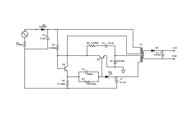
An old Nokia phone charger with a 5.6 V output was modified to provide 12 V by changing the Zener diode from a 9.1 V to a 16 V component. The circuit is mostly understood, but clarification is needed...
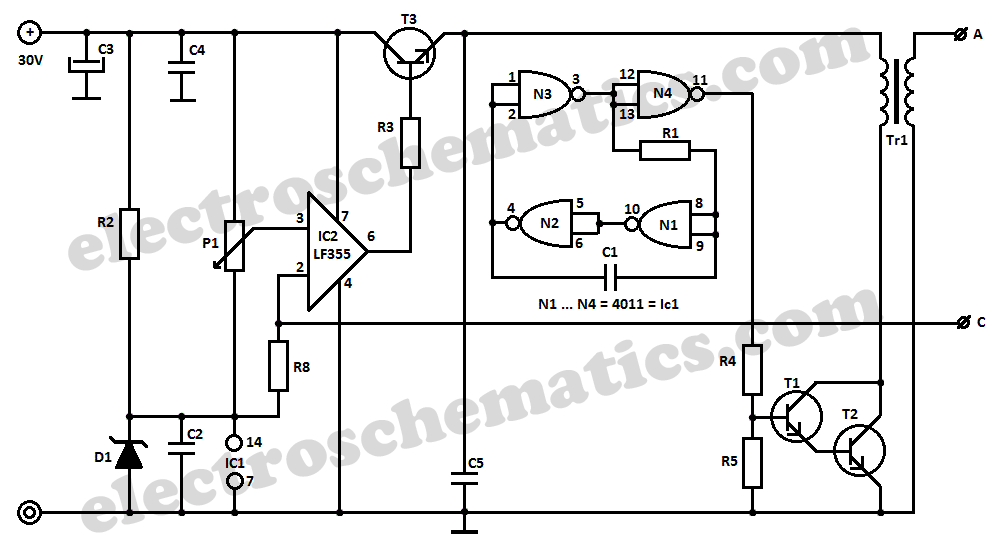
This high voltage converter circuit operates from a 30-volt power supply and can output a voltage ranging from 0 to 3 kV in version 1 or from 0 to 10 kV in version 2. The high voltage converter circuit is...
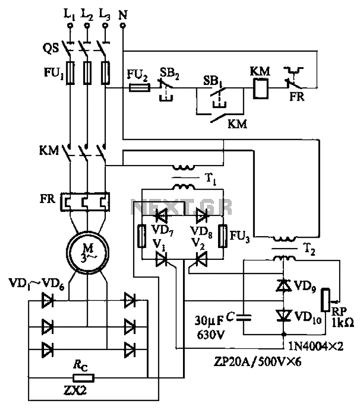
The circuit depicted in Figure 3-171 includes an auxiliary power supply that operates on single-phase AC power. It features a single-phase half-wave controlled bridge composed of diodes VD7, VD8, and thyristors V1, V2. The output current is managed by...
The AD7740 is the smallest and most affordable 12-bit Voltage-to-Frequency Converter (VFC) available. As a synchronous converter, its output frequency is tied to a fixed master clock frequency, which enhances temperature stability compared to asynchronous VFCs. With a 1...
All miniature electronic devices operate on batteries. Some require higher than standard battery voltages for efficient operation. When a battery of the required voltage is unavailable, additional cells must be connected in series to increase the DC voltage, which...
This document discusses the future direction of the Free Charge Controller project and proposes a new solar charge controller circuit. The Free Charge Controller project aims to enhance the efficiency and effectiveness of solar energy management systems. The proposed solar...
Warning: include(partials/cookie-banner.php): Failed to open stream: Permission denied in /var/www/html/nextgr/view-circuit.php on line 713
Warning: include(): Failed opening 'partials/cookie-banner.php' for inclusion (include_path='.:/usr/share/php') in /var/www/html/nextgr/view-circuit.php on line 713