
VHF 5/8wave vertical antennas
The 5/8-wavelength monopole antenna is a significant improvement over the 1/4-wavelength design, particularly in VHF applications such as those around 144 MHz. The increased length of the 5/8-wavelength antenna allows for a higher radiation resistance, which results in enhanced efficiency and gain. This antenna configuration is typically mounted vertically, and its design benefits from a ground plane that acts as a reflective surface, thereby improving the overall performance.
In terms of current distribution, the 5/8-wavelength monopole exhibits a more favorable current profile compared to the 1/4-wavelength variant. The current maximum occurs at the base of the antenna, with a gradual decrease toward the tip. This distribution contributes to the higher gain observed in the 5/8-wavelength design, as it allows for a more effective radiation pattern. The theoretical calculations supporting these findings are based on electromagnetic theory, which predicts that longer monopole antennas will radiate more efficiently when properly matched and grounded.
When designing a circuit involving these antennas, considerations must include impedance matching to ensure maximum power transfer from the transmitter to the antenna. A typical setup may involve a matching network that can include components such as capacitors and inductors to achieve the desired impedance level, often 50 ohms for most VHF applications. Additionally, the use of a balun may be necessary to convert between balanced and unbalanced lines, enabling effective connection to the transmission line.
For practical implementation, the antenna must be installed in an unobstructed location to avoid signal degradation caused by nearby structures or vegetation. Proper grounding is also essential to minimize losses and enhance performance. Overall, the choice between a 1/4-wavelength and 5/8-wavelength monopole antenna will depend on specific application requirements, including range, gain, and installation environment.At VHF, both the 1/4-wavelength monopole and the 5/8-wavelength monopole antennas are widely used. The VHF 5/8-wavelength (144 Mhz) vertical monopole has long held the reputation of providing about a 3-dB gain advantage over the 1/4-wavelength vertical monopole. The foundation of that reputation rests upon theoretical calculations that show the longer monopole to have the derived gain increase when both monopoles are set over a perfect ground.
A second factor contributing to the reputation of the longer monopole for higher gain is the current distribution along the element. Next Fig shows the distribution for both the long and short monopoles, with the ground plane elements omitted for clarity.
🔗 External reference
Related Circuits
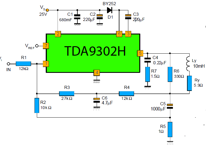
The TDA9302H is a monolithic integrated circuit housed in a HEPTAWATTTM package. It functions as a high-efficiency power amplifier designed for direct drive vertical deflection coils in television yokes. This component is suitable for use in both color and...
This compact transmitter employs a Hartley oscillator configuration. Typically, the capacitor in the tank circuit connects to the base of the transistor; however, at VHF frequencies, the base-emitter capacitance of the transistor behaves like a short circuit, maintaining its...
The vertical deflection amplifier uses a 180 degree phase splitter to generate a differential signal. The CRT requires large drive voltages, but almost no current. The oscilloscope bandwidth is limited by the amplifier chain as almost all electrostatic CRTs...
The RF stage of the receiver utilizes a transistor VT1, functioning as both a mixer and a local oscillator while also serving as a synchronous detector. A headphone cable acts as an antenna, capturing signals that are directed to...
This stage begins at the VHF antenna. The incoming VHF RF signal is preamplified and filtered and presented as the "RF" signal to the ADE and Double Balanced Mixer (DBM). The mixer also accepts the Local Oscillator's output (before...
The schematic diagram presented below illustrates a simple FM receiver constructed using four transistors. The signal from the antenna passes through the trimmer capacitor C1 before reaching the input of the first stage, which operates as a super-regenerative detector...
Warning: include(partials/cookie-banner.php): Failed to open stream: Permission denied in /var/www/html/nextgr/view-circuit.php on line 713
Warning: include(): Failed opening 'partials/cookie-banner.php' for inclusion (include_path='.:/usr/share/php') in /var/www/html/nextgr/view-circuit.php on line 713