
Ultra-Simple Oscilloscope
The schematic for the XYZ oscilloscope includes several key components that facilitate its operation. The power supply section utilizes a transformer to step down the mains voltage to the required levels for the various circuit components. The transformer outputs are connected to rectifiers that convert the AC voltage to DC, providing power to the CRT and other circuit elements. The X and Y axes are driven by a pair of operational amplifiers configured as differential amplifiers, allowing for precise control of the horizontal and vertical positioning of the electron beam on the CRT.
The Z-axis control circuit is designed to modulate the intensity of the beam, enabling the display of signals with varying amplitudes. This circuit typically includes a transistor that acts as a switch, turning the beam on and off at a high frequency to create the desired visual output. Adjustments to the Z-axis circuitry can enhance performance, particularly for more complex signal displays.
The control pots for FOCUS, ASTIG, and INTEN are connected to the CRT's deflection and intensity controls, allowing the user to optimize the display based on the input signals. The FOCUS pot adjusts the sharpness of the dot on the screen, while the ASTIG pot corrects any distortion in the shape of the dot, ensuring a clear representation of the input waveform.
The CRT itself is a critical component, with specific pin configurations that must be adhered to for proper functionality. The choice of CRT affects the oscilloscope's performance characteristics, including brightness, persistence, and overall display quality. The design accommodates various CRT types, provided they meet the specified voltage and current requirements.
In conclusion, the described XYZ oscilloscope schematic offers a practical solution for electronics enthusiasts looking to build their own oscilloscope using readily available components. With careful attention to the power supply, control circuits, and CRT selection, users can achieve a functional and reliable oscilloscope suitable for a variety of applications.Simple homemade oscilloscopes are not all that difficult to design and build. I have studied various designs dating back to the thirties and had an interest in developing a simple oscilloscope that the electronics hobbyist could build with readily available parts today. The first oscilloscope I ever built from scratch is the Tube Version shown aft er this Solid-State version on this webpage. I experimented with some solid-state designs and came up with a design shown in the schematic below. The schematic design is for a XYZ scope capable of supporting the Dutchtronix scope clock with sharp graphics and also the Version 2 TV-to-Scope converter. The Z axis design is very simple and turns the CRT grid on/off briefly. It works well with the Dutchtronix clock Z axis output and alright with NTSC video. The Z axis circuitry is definitely an area for future improvement. Before powering up the circuit for the first time, make sure the ASTIG and FOCUS pots are centered, and the INTEN pot rotated all the way towards the negative polarity of the 2.
2uF capacitor for maximum brightness. Without any inputs connected, power up the scope and adjust the X and Y position pots until a dot appears in the center of the screen, and then adjust the FOCUS pot until the dot is as sharp as possible and about 1mm in diameter. Afterwards, adjust the ASTIG pot until the dot is as round as possible, and then finally readjust all other controls to your liking.
Rather than using voltage doublers directly on the mains supply like my Version 3 XY scope design, I opted to use a power transformer for isolation safety and simplicity. I personally hate power transformers because they are large, heavy, and require special considerations when placed near an electrostatic CRT.
I would have opted for a switching power supply but switching supply transformers are not necessarily as straight-forward as a power transformer. This oscilloscope was designed around the Hammond 270X but can tolerate a wide range of transformers that meet the following requirements: Transformers with higher current capabilities on any one of the three secondaries will work as long as the voltage is close to the required specifications.
The primary winding may be chosen to suit the AC mains supply of choice, for instance, 115-120VAC for the USA. The 350VCT secondary is sufficient for the design to operate most 2 and 3 CRTs, but likely too low for any 5 CRTs.
A 550VCT secondary is a bit too high for 2 CRTs, but works nicely for 3 and some 5 CRTs. The 5V winding is used to power the 6. 3V CRT filament so it runs a bit dimmer and cooler for longer life. If preferred, the 5V and 6V windings may be swapped so the CRT filament runs at full brightness. The power supplies most likely will still work fine when running off the 5V winding. Some CRTs require an extra connection from the B+ on the PCB to the anode cap, which is detailed further below. Most American CRTs use a straightforward numbering system in which the first digit is the screen size and the number after P is the phosphor type.
To list a few common phosphors: P1 is the generic green phosphor, P4 is white, and P7 is long persistence typically used for radar. The long persistence phosphor can create interesting afterglow effects that may be desirable. Below is a phosphor chart with more information on various phosphor types. Most of the round electrostatic oscilloscope CRTs are difficult to find but are often found new old stock (NOS) from various tube suppliers or ebay.
The schematic does not detail a CRT pinout because the design works with several CRTs. The American CRT basing diagrams are shown below. If the CRT of choice is not in the American CRT basing diagram then the next best bet is to search through online tube datasheet websites. The diagrams reflect the pins of the CRT base; CRT socket pins are numbered clockwise when viewed from the bottom solder end.
So 🔗 External reference
Related Circuits
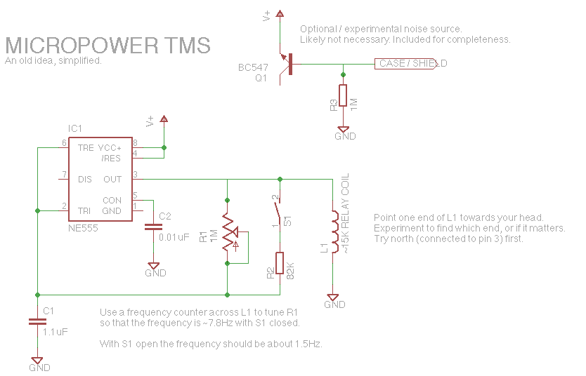
Let's face it, not every day is the greatest. Sometimes, one may not feel like doing much of anything. Wouldn't it be nice if there was a way to change brain waves at the push of a button? Transcranial...

In many oscilloscopes, the most sensitive range is between 2 to 5 mV, although it is often possible to improve this to 1 to 2 mV by using a variable gain control. To achieve even better sensitivity, the current...
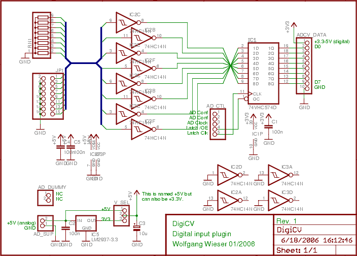
The digital input board features eight distinct digital inputs available on connector JP1. Each input is equipped with separate pull-down resistors (RN1, with a recommended value of 1 MΩ) and a Schmitt-trigger. To prevent damage from improper input voltages,...
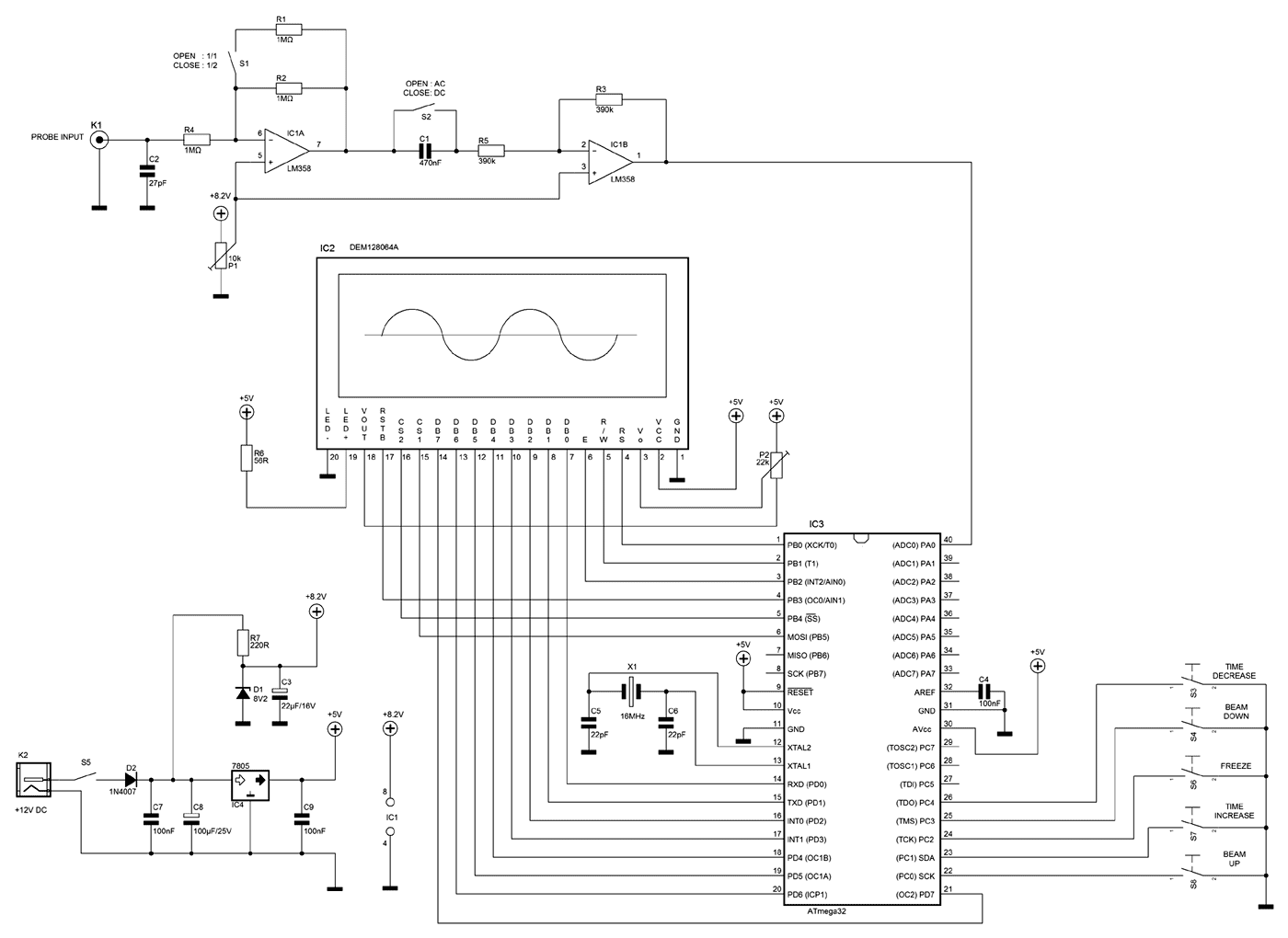
A few months ago as I was surfing on the net, I saw an oscilloscope based on PIC18F2550 microcontroller and a KS0108 controller based graphical LCD. That was Steven Cholewiak's web site. I had never seen before so amazing...
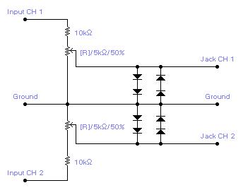
For simple electronic circuits, it may be sufficient to gain qualitative insights on dedicated electrical signals. This interface circuitry allows the line-in input of a standard PC sound card to be utilized as a 2-channel oscilloscope. Although this setup...
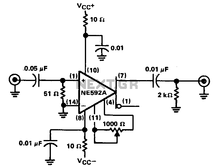
The circuit provides a voltage gain of 20 ±0.1 dB within a frequency range of 500 kHz to 50 MHz. The low-frequency response of the amplifier can be enhanced by increasing the value of the 0.05 µF capacitor connected...