
30W amplifier circuit
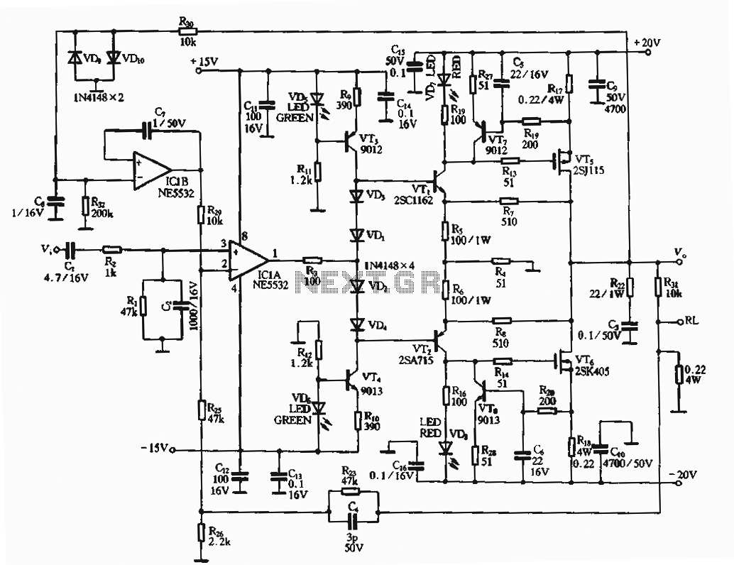
The circuit design features a robust FET amplifier configuration that enhances signal amplification while maintaining stability and reliability. The NE5532 operational amplifier is known for its low noise and high-performance characteristics, making it an ideal choice for audio and precision applications. The use of a dual-voltage power supply derived from the 15V input ensures that both positive and negative voltages are available for the biasing of the output stage, which is critical for optimal amplifier performance.
The incorporation of LEDs as voltage references not only aids in maintaining stable operation but also provides visual feedback on circuit status, which is beneficial during troubleshooting and maintenance. The push-pull configuration of the output stage allows for efficient handling of signal dynamics, reducing distortion and improving linearity.
The overload protection circuit is essential for safeguarding the output transistors from excessive current and thermal stress, ensuring long-term reliability. The feedback loop formed by R23 and C4 is crucial for stabilizing the amplifier's gain and frequency response, thus enhancing overall performance.
Additionally, the choice of VMOS transistors for the output stage is significant due to their high efficiency and fast switching capabilities, making them suitable for high-power applications. The specified parameters, including transconductance and output power, indicate that the circuit is designed to handle substantial loads while providing high fidelity and low distortion.
Overall, this circuit design exemplifies a well-thought-out approach to audio amplification, combining various elements to achieve a high-performance output stage suitable for demanding applications.The circuit is the use of FET amplifier circuit for output. NE5532 op amp using 15V power supply, pushing its output FET output stage after stage voltage amplification. Voltage output stage bias circuit of the input from the pre-stage of 15V, after VT3, VT4 voltage bias circuit to supply. Positive and negative voltage regulator VT3, VT4 uses two LED as a voltage reference, LED not only has good electrical voltage characteristics, and can be used as an indication of the operation of the circuit using this power supply circuit o become not only the excellent performance of constant voltage bias circuit, and it will serve as a pre-stage of the constant current source load, increase the gain of the output stage. Vn, VTz composed of push-pull output stage driven, it is also a common emitter circuit having a voltage amplification capabilities.
Vr7, VTs composition overload protection circuit output tube. ICIb (lf / NE5532) composed 0:00 servo circuit. R23.C4 composition and a negative feedback circuit. VMOS on the tube output stage using 2SJ115 and 2SK405 0 can also be used IRF9130 and IRF130, parameters: transconductance 4, pressure loOvPCM = 75W, Iau = 9A. When debugging, measuring the voltage drop across the resistor is 0.22fl to 40 ~ 50mV.
Related Circuits
There are two types of preamplifiers for magnetic phono cartridges. The most common type includes an RIAA equalization network in the feedback loop, as described in the March 2002 issue of SILICON CHIP. The second type, previously used in...
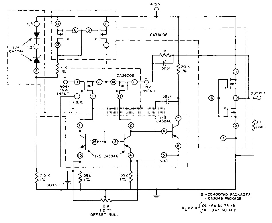
This unity-gain follower amplifier features a CMOS p-channel input, an NPN second-gain stage, and a CMOS inverter output. The integrated circuit components consist of two CA3600E CMOS transistor pairs and a CA3046 NPN transistor array. A zener-regulated leg provides...
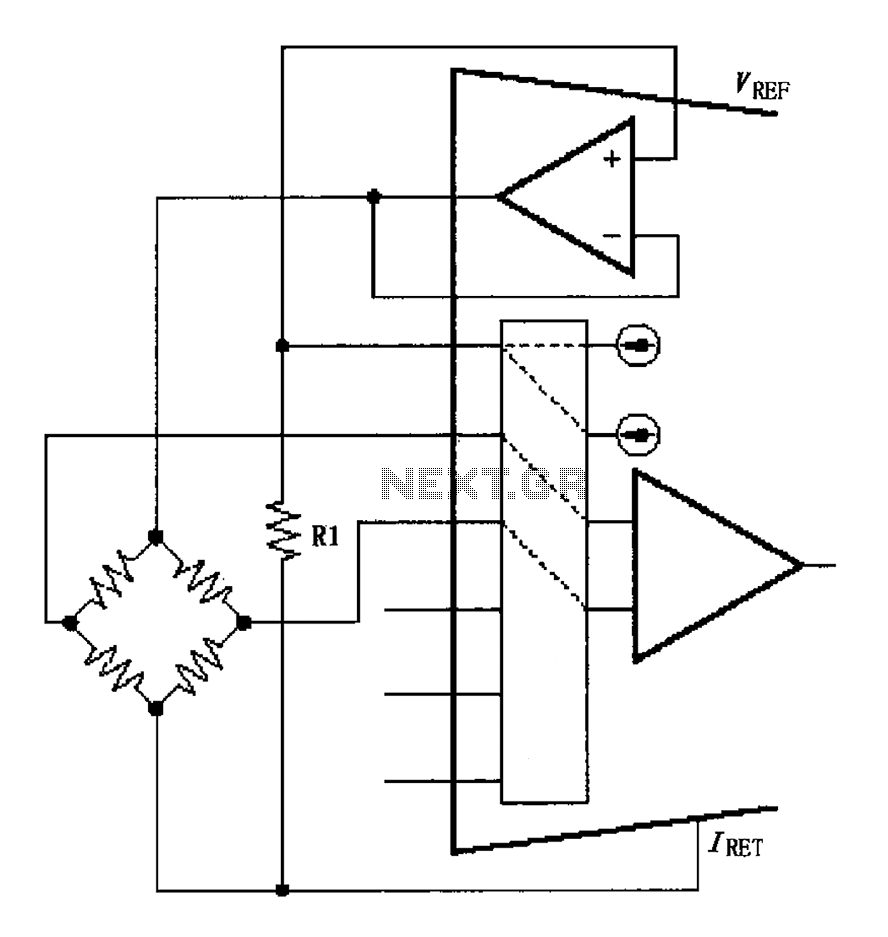
The circuit for the bridge excitation voltage XTR108 is linearized using adjusted algorithms that correspond to the linearization of the RTD response. The excitation voltage VEX is defined as 2IREFR1, where VEX represents the excitation voltage applied at both...
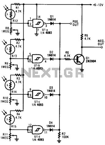
This light-dependent sensor utilizes light-dependent resistors (LDRs) to detect the presence or absence of light. The alarm remains inactive as long as the light source illuminating the LDRs is constant. However, if the light is interrupted, the alarm is activated. The...
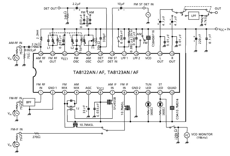
A simple low-power AM/FM radio receiver electronic project can be designed using the TA8122 integrated AM/FM receiver, manufactured by Toshiba Semiconductor. This radio receiver circuit can be utilized for portable radio applications or similar devices. The TA8122 radio receiver...
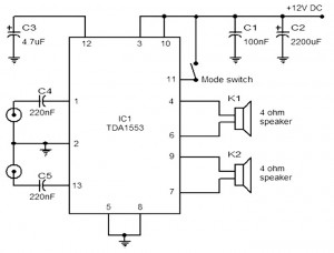
The provided schematic represents a car stereo amplifier circuit that can be utilized in cars or other vehicles. The circuit is based on the TDA1553, which is a Class-B audio amplifier. This circuit is straightforward, consisting solely of the...